Integrated battery charging and discharging equipment

A charging and discharging equipment, charging and discharging technology, applied in the direction of measuring electricity, measuring electrical variables, measuring devices, etc., can solve the problems of crossing and misalignment of charging and discharging cables, low overall efficiency of equipment, high energy loss, etc., to avoid wiring errors, Reduce electricity costs and reduce space occupancy

Pending Publication Date: 2019-05-24
惠州市鼎力智能科技有限公司
View PDF0 Cites 1 Cited by
  • Summary
  • Abstract
  • Description
  • Claims
  • Application Information

AI Technical Summary

Problems solved by technology

The power supply part is separated from the mechanical part, occupying a large area
Moreover, the connecting cable between the power supply and the fixture of the mechanical part is very long, the cost of the cable is high, the energy loss caused by the cable during charging and discharging is high, and the overall efficiency of the equipment is low
In addition, the charging and discharging cables may cross and be miswired, and the maintenance is complicated, which is likely to cause safety hazards

Method used


Image

  • Integrated battery charging and discharging equipment
  • Integrated battery charging and discharging equipment
  • Integrated battery charging and discharging equipment

Examples


Embodiment 1

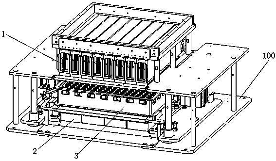
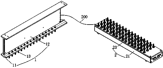
[0034] A kind of integrated battery charging and discharging equipment of this embodiment, its overall structural diagram sees figure 1 As shown, it includes a machine tool 100 , and a positive electrode module 1 and a negative electrode module 2 arranged on the machine tool 100 . The positive module 1 and the negative module 2 correspond to each other, and the positive module 1 and the negative module 2 are arranged on the worktable of the machine tool 100 through guide columns, and can be closed or separated from each other. Between the positive electrode module 1 and the negative electrode module 2 is a three-dimensional station for battery charge and discharge testing. Temperature and smoke detectors can be installed in the test station to sense fire safety hazards. Moreover, in some embodiments, the negative module 2 and the positive module 1 can be highly integrated, that is, the negative module 2 is integrated on the positive module 1. At this time, between the positive...

Embodiment 2

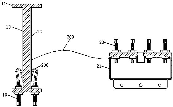
[0046] This embodiment is the same as Embodiment 1, the difference is that, see Figure 4 As shown, the common power supply PCB of the positive power supply part 12 and the negative power supply part 22 is fixedly installed on the positive pole module support body 11, and one end of the chuck of the positive pole clamp part 13 of the positive pole module 1 is in contact with the positive pole of the power supply PCB. .

[0047] And, specifically, the negative electrode module support member 21 is a housing, one end of the chuck of the negative electrode clamp part 23 is installed on the negative electrode module support part 21, and the other end extends out of the negative electrode module support part 21, and the negative electrode clamp part 23 The collet is connected to the negative interface of the common power supply PCB on the positive module 1 through the connection line 200 . Therefore, the integrated arrangement of the power supply part and the mechanical fixture pa...

Embodiment 3

[0049] This embodiment is the same as Embodiment 1, the common power supply PCB of the positive power supply part 12 and the negative power supply part 22 is fixedly installed on the positive pole module support body 11, the difference is that, see Figure 5 As shown, on the positive electrode module 1 , the collet of the positive electrode fixture part 13 is fixedly installed on the positive electrode module support body 11 , and the positive interface of the common power supply PCB is connected and installed on the collet of the positive electrode fixture part 13 .

[0050] And, specifically, the negative electrode module support member 21 is a housing, one end of the chuck of the negative electrode clamp part 23 is installed on the negative electrode module support part 21, and the other end extends out of the negative electrode module support part 21, and the negative electrode clamp part 23 The chuck of the clamp is connected to the negative pole of the common power supply...


PUM


Abstract

The invention discloses integrated battery charging and discharging equipment which comprises a machine tool, a positive electrode module and a negative electrode module. The positive electrode moduleand the negative electrode module are arranged on the machine tool, correspond to each other and can slide to be mutually folded or unfolded, each of the positive electrode module and the negative electrode module comprises a module supporting body, a power source portion and a clamp portion, each power source portion and the corresponding clamp portion are integrated on the corresponding modulesupporting body and connected, and the clamp portion of the positive electrode module and that of the negative electrode module are used for clamping a positive electrode and a negative electrode of abattery in a contact manner for charging and discharging of the battery. The power source portion of the battery charging and discharging equipment is integrated with a mechanical portion, so that space occupation rate is small, and consumption of various cables is reduced greatly; a charging and discharging loop is short, so that charging and discharging efficiency of the equipment is improved,and power consumption cost of clients is lowered; the whole equipment is few in wire rod, easy to maintain and low in maintenance cost, wiring errors during equipment maintenance are avoided, and working safety of the equipment is improved.

Description

technical field [0001] The invention relates to the technical field of charging and discharging equipment for secondary batteries, in particular to an integrated battery charging and discharging equipment. Background technique [0002] At present, the existing charging and discharging (chemical composition and capacity) equipment used in automated large-scale production is mainly composed of three parts: tray, power supply department and mechanical (fixture / press) department. Among them, the tray is the carrier of the battery, which can generally accommodate dozens to hundreds of batteries according to different battery specifications; the power supply part is composed of multiple constant current and constant voltage sources, which can provide power and load for battery charging and discharging; mechanical ( The clamp / press) part can hold the tray, and there are multiple sets of battery positive and negative clamps on it. After the action, the clamps on it can clamp the ent...

Claims


Application Information

Patent Timeline
IPC IPC(8): G01R31/385G01R1/04
Inventor 曾爱良余进江孔敏周济峰龙澄埃谭志亮
Owner 惠州市鼎力智能科技有限公司
Why Eureka
Try Eureka