DC permanent magnet motor stator assembling machine

A permanent magnet motor and stator group technology, which is applied in the manufacture of stator/rotor bodies, etc., can solve the problems of poor product quality consistency, low production efficiency, and high labor costs

Inactive Publication Date: 2019-05-24
四川圣锦高新科技股份有限公司
View PDF4 Cites 10 Cited by
  • Summary
  • Abstract
  • Description
  • Claims
  • Application Information

AI Technical Summary

Problems solved by technology

In the prior art, the assembly of the DC permanent magnet motor stator is generally done manually. Although this assembly method has the advantage of no fixed investment in equipment, it also has technical problems such as low production efficiency, high labor costs, and poor product quality consistency. , the invention provides a DC permanent magnet motor stator assembly machine

Method used


Image

  • DC permanent magnet motor stator assembling machine

Examples


Embodiment 1

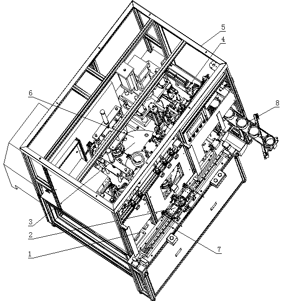
[0039] Such as figure 1 As shown, a DC permanent magnet motor stator assembly machine includes a frame 5, and also includes:

[0040] Gluing device 1 is used to glue the casing;

[0041] The first assembly device 2 is used to realize the installation of the magnetic tile on the magnetic tile frame;

[0042] The second assembly device 3 is used to realize the assembly of the magnetic tile frame and the casing;

[0043] The magnetizing device is used to realize the magnetization of the magnetic tile;

[0044] A detection device is used to realize the detection of the residual magnetism of the magnetic tile;

[0045] Riveting device, used to realize the installation of riveting screws on the stator;

[0046] The output device 4 is used to output the riveted stator;

[0047] The transfer device is used to transfer the casing on the gluing device 1 and the magnetic tile frame that has completed the installation of the magnetic tiles to the second assembly device 3. After the a...

Embodiment 2

[0051] The present embodiment is further limited on the basis of embodiment 1, as figure 1 As shown, as a specific implementation form of the transmission device: the transmission device includes a linear transmission part and a circular transmission part;

[0052] The first assembly device 2 includes a clamp for clamping the magnetic tile rack, the clamp is installed on the linear transmission part, and under the action of the linear transmission part, the magnetic tile rack can perform linear motion;

[0053] The circular transfer part includes a turntable 6 and a casing clamping station arranged on the turntable 6;

[0054] The second assembling device 3 , magnetizing device, detecting device, and riveting device are sequentially arranged circularly around the turntable 6 , and during the rotation of the turntable 6 , the casing is completed in the second assembling device 3 , magnetizing device, detecting device, Transfer between riveting devices. This scheme provides a ...


PUM


Abstract

The invention discloses a DC permanent magnet motor stator assembling machine, and the assembling machine comprises a rack and further comprises a gluing device for gluing a shell; a first assemblingdevice for realizing the installation of a magnetic shoe on a magnetic shoe rack; a second assembling device for assembling a magnetic shoe rack and the shell; a magnetizing device; a detection devicefor detecting the residual magnetism intensity of the magnetic shoe; a riveting device; an output device; and a conveying device, wherein the gluing device, the first assembling device, the second assembling device, the magnetizing device, the detection device, the riveting device, the output device and the conveying device are arranged on the rack. The assembling machine can realize assembly line assembly of the DC permanent magnet motor stator.

Description

technical field [0001] The invention relates to the technical field of assembly equipment, in particular to a DC permanent magnet motor stator assembly machine. Background technique [0002] Permanent magnet DC motors can be divided into permanent magnet brushless DC motors and permanent magnet brushed DC motors according to whether they have brushes or not. A permanent magnet DC motor is a DC motor that uses permanent magnets to create a magnetic field. Permanent magnet DC motors are widely used in various portable electronic equipment or appliances, such as tape recorders, VCD players, record players, electric massagers and various toys, and are also widely used in automobiles, motorcycles, hand dryers, electric bicycles, batteries Vehicles, ships, aviation, machinery and other industries are also widely used in some high-end products, such as video recorders, copiers, cameras, mobile phones, precision machine tools, bank currency counters, banknote binding machines, etc....

Claims


Application Information

Patent Timeline
IPC IPC(8): H02K15/03
Inventor 喻文才
Owner 四川圣锦高新科技股份有限公司
Why Eureka
Try Eureka