Building block type stator disc, permanent magnet motor and speed control method of permanent magnet motor

A permanent magnet motor, building block technology, applied in the field of permanent magnet motor and its speed control, building block stator disk, can solve problems such as affecting the working efficiency of the motor, low magnetic flux, limited coils, etc., and achieve simple and convenient forward and reverse control. The effect of increasing the magnetic flux and increasing the number of arranged turns

Inactive Publication Date: 2019-05-24
高宪立
View PDF2 Cites 2 Cited by
  • Summary
  • Abstract
  • Description
  • Claims
  • Application Information

AI Technical Summary

Problems solved by technology

It is necessary to convert the DC power into the required three-phase AC power, and then drive the motor to run, the cost is relatively high
Moreover, the number of coils wound on each stator tooth of the stator disk is limited, and the material is not well utilized to wind more coils, and the magnetic flux is low, which affects the working efficiency of the motor

Method used


Image

  • Building block type stator disc, permanent magnet motor and speed control method of permanent magnet motor
  • Building block type stator disc, permanent magnet motor and speed control method of permanent magnet motor
  • Building block type stator disc, permanent magnet motor and speed control method of permanent magnet motor

Examples


Embodiment Construction

[0038] The present invention will be described in detail below in conjunction with the accompanying drawings and specific embodiments.

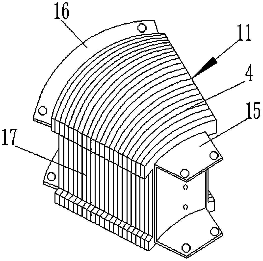
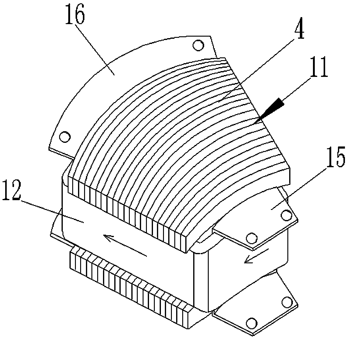
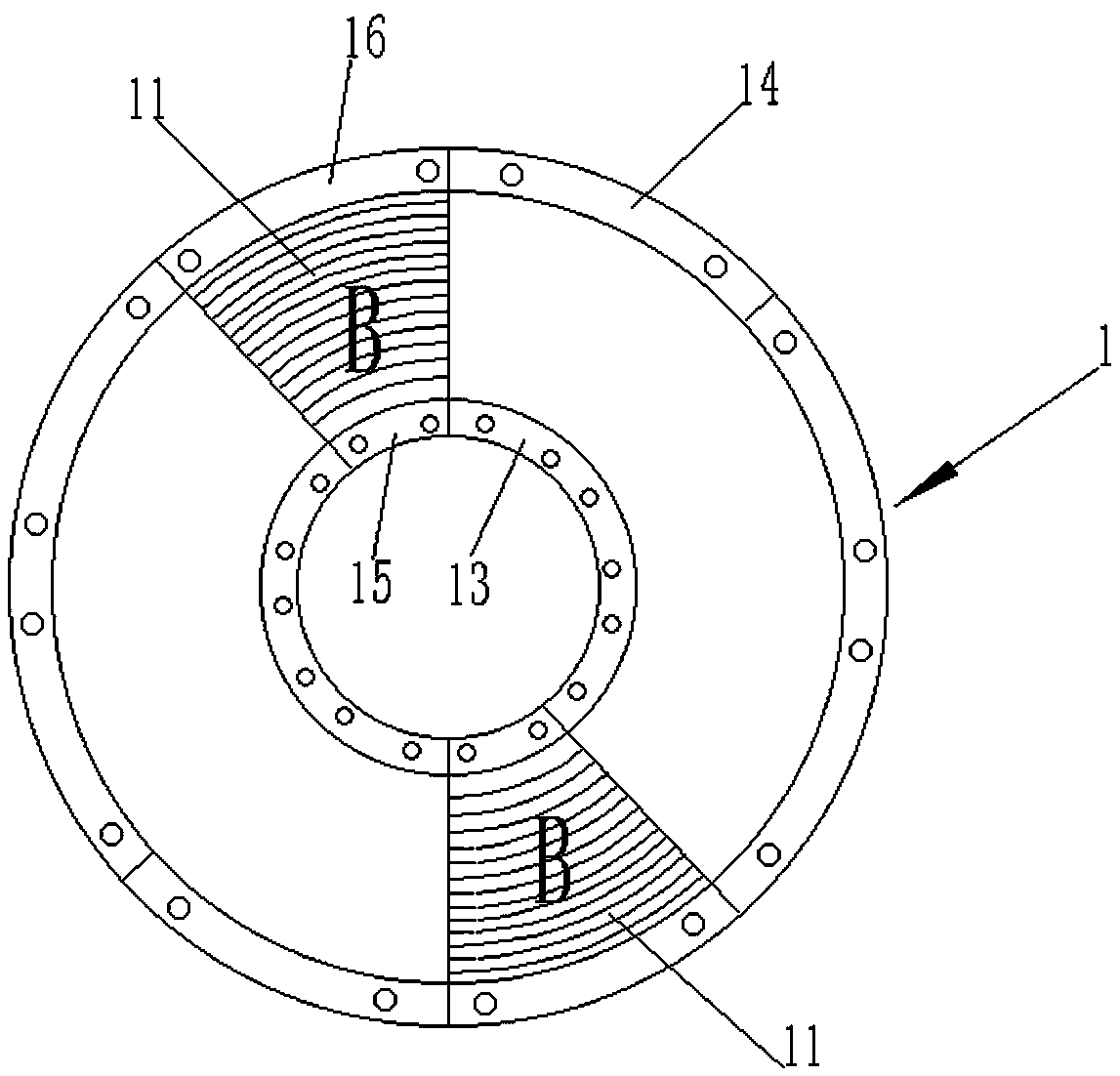
[0039] see Figure 1-5 and Figure 9 , a building block stator disk, including a number of stator teeth 11, a winding 12 wrapped on each stator tooth 11 parallel to the direction of the rotor disk 2, an inner fixed ring frame 13 and an outer fixed ring frame 14 arranged inside and outside; The stator tooth 11 is arranged between the inner fixed ring frame 13 and the outer fixed ring frame 14 and forms a ring; one end of the stator tooth 11 is fixedly connected to the inner fixed ring frame 13 through the first connecting piece 15, and the other end of the stator tooth 11 One end is fixedly connected to the outer fixing ring frame 14 through the second connecting piece 16 . The stator teeth 11 are formed by superimposing and fixing several stator punches.

[0040] A groove 17 for wrapping the winding 12 is provided on the periphery of the m...


PUM


Abstract

The invention relates to a building block type stator disc, a permanent magnet motor and a speed control method of the permanent magnet motor. The building block type stator disc comprises a pluralityof stator teeth. Windings which are parallel to the direction of the rotor disc are wound on each stator tooth. An inner fixing ring frame and an outer fixing ring frame are sleeved inside and outside the stator disc. The plurality of stator teeth are arranged between the inner fixing ring frame and the outer fixing ring frame to form an annular shape. One end of each stator tooth is fixedly connected to the inner fixing ring frame through a first connecting piece, and the other end of each stator tooth is fixedly connected to the outer fixing ring frame through a second connecting piece. Thepermanent magnet motor is simple in structure and convenient to control. The field of the permanent magnet motor does not need to be converted into a rotating magnetic field. Different from the control mode of a traditional permanent magnet motor, a motor can be driven to rotate through continuously changing a coil on different magnetic poles. Therefore, the cost is low and the maintenance is convenient.

Description

technical field [0001] The invention relates to a building block type stator plate, a permanent magnet motor and a speed control method thereof, belonging to the field of permanent magnet motors. Background technique [0002] Compared with the electric excitation motor, the permanent magnet motor has the advantages of simple structure, reliable operation, small size, light weight, low loss, high efficiency, flexible shape and size of the motor, etc., so the application range is extremely wide, almost all over the world Aerospace, defense, and various fields of daily life such as power generation, elevators, and electric vehicles. [0003] The driving principle of the existing permanent magnet motors is that after the winding on the stator disk is connected to a three-phase symmetrical alternating current, a rotating magnetic field will be generated, and the rotating magnetic field will drive the rotor disk to rotate. For example, the permanent magnet stack described in the p...

Claims


Application Information

Patent Timeline
Patent Type & Authority Applications(China)
IPC IPC(8): H02K16/00H02K1/14H02K1/18H02K1/27H02P6/30H02P6/17
CPCH02K1/146H02K1/182H02K1/2793H02K16/00H02P6/17H02P6/30
Inventor 高宪立
Owner 高宪立
Why Eureka
Try Eureka