
A painting process for product coating

A process and product technology, applied in spray booths, spray devices, etc., can solve problems such as different processing times

Active Publication Date: 2020-07-14
SHANGHAI ZHENHUA PORT MACHINARY HEAVY IND CO LTD
View PDF4 Cites 0 Cited by
  • Summary
  • Abstract
  • Description
  • Claims
  • Application Information

AI Technical Summary

Problems solved by technology

[0006] In view of the above-mentioned defects existing in the prior art, the purpose of the present invention is to provide a painting process flow for product coating, which solves the problem of circulation between the various processes of the workshop coating line, and further solves the problem that the processing time of each process is different, and the production line better flow

Method used


Image

  • A painting process for product coating
  • A painting process for product coating

Examples


Embodiment Construction

[0024] The technical solutions of the present invention will be further described below in conjunction with the accompanying drawings and embodiments.

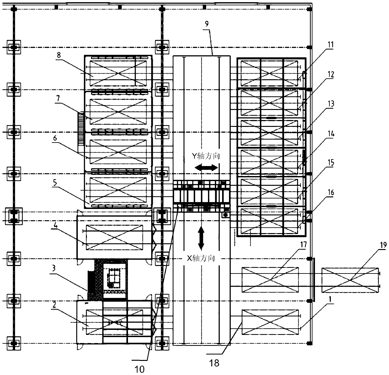
[0025] Please combine Figure 1 to Figure 2 Shown, a kind of product coating process flow of painting provided by the present invention:

[0026] First lay the power trolley track 9, and set corresponding stations along the two sides of the power trolley track 9X axis direction, specifically:

[0027] Along one side of the 9X-axis direction of the power trolley track, a grinding room station 2, a paint spraying room station 3 and four drying room stations (drying room station one 5, drying room station two 6 , drying room station three 7, drying room station four 8). Along the other side of the power trolley track 9X axis direction, a loading station 1, a discharge buffer station 17 and six self-drying room stations (self-drying room station-11, self-drying room station Two 12, self-drying room station three 13, self-drying...


PUM


Abstract

The invention discloses a painting process flow for product painting; a product on a feeding station is moved to a polishing chamber station by a power trolley for surface cleaning operation, the product is moved to a painting chamber station by the power trolley for painting operation according to requirements after completion, the product is moved to a drying chamber station by the power trolleyfor automatic drying according to paint drying requirements after completion, and the product is moved to a self-drying chamber station by the power trolley for drying after completion; after completion, the product is moved to a unloading buffer station or a unloading station by the power trolley to load and unload the product after painting is completed, and the power trolley returns to the loading station to cycle the next batch of products, and the cycle reciprocates accordingly. According to the invention, the problem of circulation among each working procedure of a workshop painting assembly line is solved, and the problem that the processing time of each working procedure is different is further solved, so that the assembly line can be circulated well.

Description

technical field [0001] The invention relates to product painting process technology, more specifically, relates to a product painting process flow. Background technique [0002] At present, the drying method of product spraying is mainly self-drying, which has long production cycle, low turnover rate, very large occupied site and production area, backward technology and low efficiency, and it is difficult to effectively guarantee the coating quality. [0003] At the same time, the painting operation adopts an open floor booth operation, and the open construction environment in the workshop causes paint mist to pollute other components during cross-operation, and VOCS is directly emitted into the workshop, without good collection measures, forming fugitive emissions, which is serious It does not comply with national and local environmental and ecological laws and regulations, which affects the physical and mental health of workers. Unorganized emission of waste gas, multi-ar...

Claims


Application Information

Patent Timeline
Patent Type & Authority Patents(China)
IPC IPC(8): B05B16/20B05B13/02
Inventor 杨晓华王绪光王传存廖友辉
Owner SHANGHAI ZHENHUA PORT MACHINARY HEAVY IND CO LTD
Learn More