Check patentability & draft patents in minutes with Patsnap Eureka AI!

A Single Inductor Multiple Output DC-DC Buck Converter

A single-inductor multi-output, DC step-down technology, applied in the field of electronics, can solve the problems of long turn-on time of the power tube, affecting branch modulation, and other branch modulation errors, and achieve the effect of suppressing the cross-modulation effect.

Active Publication Date: 2020-09-15
SOUTH CHINA UNIV OF TECH
View PDF4 Cites 0 Cited by
  • Summary
  • Abstract
  • Description
  • Claims
  • Application Information

AI Technical Summary

Problems solved by technology

In single-channel charging, only one secondary branch is turned on in a primary cycle, and then each secondary branch is turned on in different cycles; in multi-channel charging, in a primary cycle, the secondary branches are sequentially turned on. Compared with the former, it can have a larger load range and higher efficiency expectations, but because the output branches share the inductor current in one cycle, when the load of one output changes, the inductor current change speed is limited, and it is inevitable It will cause modulation errors in other branches. This effect is called cross modulation (CrossRegulation). This effect is addressed by many control methods.
[0004] In addition, when the overall output load is heavy, but the load of a certain branch is light, because the duty ratio of the power tube of the output branch is related to the ratio of the output current of the branch to the total inductor current, there will be some branch duty ratios. If it is too small, the large-sized power tube will be turned on for too long (greater than the actual duty cycle), or it will not be able to turn on, resulting in the failure of the modulation of this channel, which will affect the modulation of other branches. This effect is the modulation failure of unbalanced loads. solve

Method used


Image

  • A Single Inductor Multiple Output DC-DC Buck Converter
  • A Single Inductor Multiple Output DC-DC Buck Converter
  • A Single Inductor Multiple Output DC-DC Buck Converter

Examples


Embodiment Construction

[0044] The present invention will be further described below in conjunction with the accompanying drawings and specific embodiments.

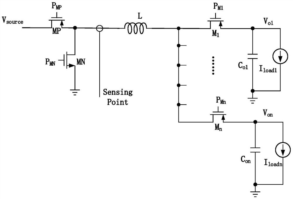
[0045] refer to figure 1 and figure 2 , this embodiment shows a single-inductor multiple-output DC-DC buck converter, in this embodiment, the single-inductor multiple-output DC-DC buck converter includes a primary power circuit, a plurality of secondary branches and control section, where the primary power circuit and multiple secondary branches such as figure 1 As shown, the control part is as figure 2 As shown, it includes current sensor, primary power tube controller, secondary power tube controller, mode controller, bandgap reference source, power tube dead zone controller, primary power tube drive circuit and secondary power tube drive circuit. Wherein, the primary power circuit includes two primary power transistors, that is, a PMOS transistor MP, an NMOS transistor MN and an energy storage inductor L. Multiple secondary branches a...


PUM


Abstract

The invention discloses a single-inductor multi-output DC-DC buck converter, which comprises a main-stage power circuit, multiple secondary branches, a current sensor, a band-gap reference source, a primary power tube controller, a secondary power tube controller and a mode controller, wherein the primary power tube controller is used for controlling a power tube of a primary power circuit to be turned on or turned off according to an output current signal of the current sensor and error signals of output voltages of the plurality of secondary branches so as to adjust energy transmitted to anenergy storage inductor from the input end of the primary power circuit; the secondary power tube controller is used for controlling power tubes of the secondary branches to be turned on or turned off; the error signals of the output voltages of the plurality of secondary branches are output according to the output voltages of the plurality of secondary branches; and the mode controller is used for generating a time sequence of pulse width modulation and fixed on-time modulation. According to the invention, the problems of modulation failure and cross modulation effect of the unbalanced load can be overcome, and the method can be widely applied to the technical field of electronics.

Description

technical field [0001] The invention relates to the field of electronic technology, in particular to a single-inductance multi-output DC-DC step-down converter. Background technique [0002] Single Inductor Multiple Output (Single Inductor Multiple Output, SIMO) DC-DC step-down converter is a switch-type DC step-down conversion circuit that generates multiple types of DC output voltages through a DC input voltage. Its characteristic is that it only contains An inductor and a plurality of capacitors have high efficiency and efficient layout area utilization, which conforms to the trend of highly integrated system design. [0003] Single-inductor multi-output DC-DC converters can be divided into two modes: single charge and multiple charge, according to the waveform of the inductor current within one cycle. In single-channel charging, only one secondary branch is turned on in a primary cycle, and then each secondary branch is turned on in different cycles; in multi-channel ch...

Claims


Application Information

Patent Timeline
IPC IPC(8): H02M3/157H02M3/158
Inventor 刘育洋李斌郑彦祺吴朝晖
Owner SOUTH CHINA UNIV OF TECH
Features
  • R&D
  • Intellectual Property
  • Life Sciences
  • Materials
  • Tech Scout
  • Unparalleled Data Quality
  • Higher Quality Content
  • 60% Fewer Hallucinations
Learn More