Visible light data receiving and transmitting terminal

A technology of data sending and receiving and visible light, applied in the field of visible light communication, can solve the problems of increasing product cost, increasing LED brightness, increasing optical receiving system, etc., and achieves the effects of low cost, best anti-interference effect and high sensitivity

Active Publication Date: 2019-05-28
烟台有光通信科技有限公司
View PDF7 Cites 0 Cited by
  • Summary
  • Abstract
  • Description
  • Claims
  • Application Information

AI Technical Summary

Problems solved by technology

[0014] First of all, increasing the power of the transmitting system requires the use of higher power driver chips, which will increase product costs; secondly, many application scenarios of visible light communication technology need to realize wireless optical communication without affecting LED lighting, and excessively increase the power of the transmitting system. 、Increasing the brightness of the LED may have a certain impact on the lighting
That is, the solution of adding an optical receiving system will make the cost of the optical system more expensive on the one hand, and will also reduce the optical signal receiving range of the receiving system on the other hand.

Method used


Image

  • Visible light data receiving and transmitting terminal
  • Visible light data receiving and transmitting terminal

Examples


Embodiment Construction

[0037] The principles and features of the present invention are described below in conjunction with the accompanying drawings, and the examples given are only used to explain the present invention, and are not intended to limit the scope of the present invention.

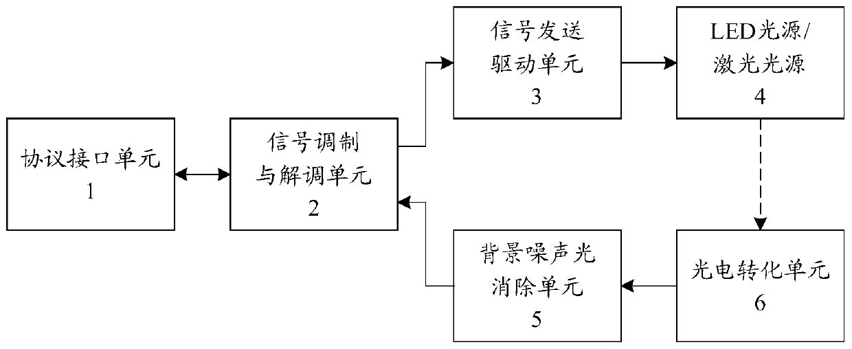
[0038] Please refer to figure 1 As shown, it is a schematic structural diagram of the visible light data transceiving terminal of the present invention. The visible light data transceiver terminal includes: a protocol interface unit 1, a signal modulation and demodulation unit 2, a signal transmission drive unit 3, an LED light source / laser light source 4, a background noise optical elimination unit 5, and a photoelectric conversion unit 6, wherein,

[0039] The protocol interface unit 1 is used to input / output digital signals according to the serial port protocol, the protocol interface unit 1 is electrically connected to the signal modulation and demodulation unit 2, and exchanges digital signals with the signal m...


PUM


Abstract

The visible light data receiving and transmitting terminal comprises a protocol interface unit, a signal modulation and demodulation unit, a signal sending driving unit, an LED light source, a background noise light eliminating unit and a photoelectric conversion unit. The protocol interface unit inputs / outputs a digital signal according to a serial port protocol and is electrically connected to the signal modulation and demodulation unit; Wherein the signal modulation and demodulation unit modulates and demodulates a digital signal and sends the digital signal out, the signal modulation and demodulation unit is at least provided with three terminals, and the first terminal is an input / output end and is electrically connected with the protocol interface unit; The second terminal is an output end and is electrically connected to the input end of the signal sending driving unit; The third terminal is an input end and is electrically connected to the output end of the background noise light eliminating unit; The signal sending driving unit is electrically connected to the LED light source, and the photoelectric conversion unit receives light signals sent by the LED light source and converts the light signals into electric signals. And the input end of the background noise light eliminating unit is electrically connected to the output end of the photoelectric conversion unit.

Description

technical field [0001] The present invention relates to the technical field of visible light communication, in particular to a visible light data transceiving terminal capable of eliminating ambient light interference. Background technique [0002] Visible light communication technology mostly uses white light LED as the light source, and uses the communication signal carried by the LED light to directly modulate the luminous intensity of the LED to transmit information. The specific implementation method is generally by implanting a chip module in the LED lamp, driving the LED to send out a high-speed bright and dark flashing signal invisible to the naked eye, and then using a photoelectric sensor in the receiving system to identify the signal light, and the LED is off (no signal light) to indicate When the number "0" is on, the LED lights up (with signal light) to represent the number "1", thereby realizing the transmission of digital signals. [0003] Visible light commu...

Claims


Application Information

Patent Timeline
IPC IPC(8): H04B10/40H04B10/116
Inventor 尤明赵传强
Owner 烟台有光通信科技有限公司
Why Eureka
Try Eureka