High-precision clock synchronization method and system for communication equipment
A high-precision clock and communication equipment technology, applied in time division multiplexing systems, synchronization devices, wireless communications, etc., can solve the problem of increasing the frequency and time output deviation of a single site, difficult to meet high-precision clock synchronization requirements, and back Insufficient board terminals to achieve the effect of improving utilization, saving backplane terminals, and improving clock synchronization accuracy
- Summary
- Abstract
- Description
- Claims
- Application Information
AI Technical Summary
Problems solved by technology
Method used
Image

Examples
Embodiment 1
[0039] In this method, the process of the clock unit sending the transmission delay value to the service disk includes:
[0040] The clock unit periodically selects a service disk; when the service disk detects that the clock signal can be transmitted with the clock unit (conditions that can be transmitted, such as the bus used to transmit the clock signal between the service disk and the clock unit is not occupied) , upload the clock signal to the clock unit; the clock unit sends the corresponding transmission delay value to the service disk after receiving the clock signal.
[0041]It can be seen from this that the present invention only issues the transmission delay value to one service disk each time and performs phase compensation, the phase compensation logic is relatively simple, the coupling degree is low, and it is convenient for people to use; meanwhile, the present invention periodically The phase compensation of the clock signal of the service disk is carried out, ...
Embodiment 2
[0043] In this method, when the hardware physical transmission delay of the clock sending signal and the clock signal is the same, and the initial output clock of the service disk is consistent with the phase of the input clock, the calculation formula of the transmission delay value T is: T=T1 / 2, T1 is the clock transmission signal sent by the clock unit, and the clock phase difference between the clock signal and the clock signal uploaded by the service disk. When the hardware physical transmission paths of the clock sending signal and the clock signal are different, the transmission delay value can also be obtained according to other calculation methods related to T1.
[0044] It can be seen from this that those skilled in the art can clearly calculate and obtain the transmission delay value according to the above calculation formula.
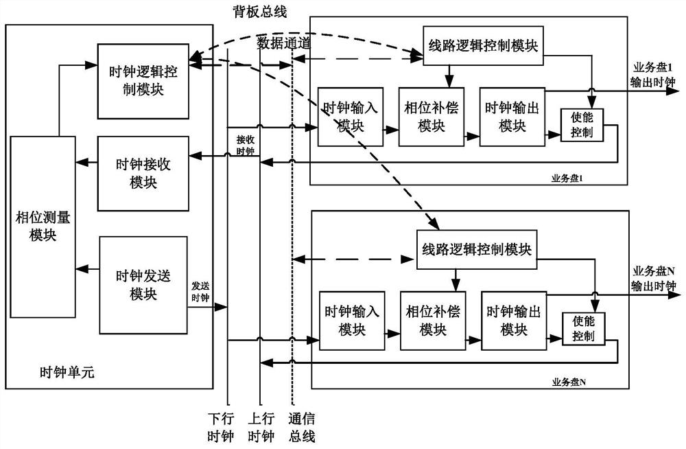
[0045] see figure 1 As shown, the high-precision clock synchronization system of the communication device in the embodiment of the present...
Embodiment 3
[0052] see figure 1 As shown, the clock unit also includes a clock sending module and a clock receiving module, and the service tray also includes a clock input module and a clock output module.
[0053] The clock sending module is used to: send the clock sending signal to the phase measurement module, and also send the clock sending signal to the service disk through the downlink clock bus. For the integrity and reliability of the clock sending signal, the clock sending module will always pass the downlink clock bus Send the clock to send the signal;
[0054] The clock input module is used to: send the clock transmission signal issued by the clock transmission module to the phase compensation module;
[0055] The clock output module is used to: upload the clock signal formed by the phase compensation module to the clock unit;
[0056] The clock receiving module is used for sending the clock signal to the phase measurement module after receiving the clock signal through the ...
PUM
 Abstract
Description
Claims
Application Information
 - R&D
- Intellectual Property
- Life Sciences
- Materials
- Tech Scout
- Unparalleled Data Quality
- Higher Quality Content
- 60% Fewer Hallucinations
Browse by: Latest US Patents, China's latest patents, Technical Efficacy Thesaurus, Application Domain, Technology Topic, Popular Technical Reports.
© 2025 PatSnap. All rights reserved.Legal|Privacy policy|Modern Slavery Act Transparency Statement|Sitemap|About US| Contact US: help@patsnap.com