A step-by-step pressurized pneumatic infusion device

A technology of an infusion device and a compression cavity, applied in the field of medical devices, can solve the problems of blood backflow, increase the burden on the heart, shorten the infusion time, etc., and achieve the effects of increasing gas pressure and facilitating movement and portability.

Active Publication Date: 2021-04-30
ZHEJIANG NORMAL UNIVERSITY
View PDF11 Cites 0 Cited by
  • Summary
  • Abstract
  • Description
  • Claims
  • Application Information

AI Technical Summary

Problems solved by technology

This infusion mode will bring many problems in actual use: the flow rate is adjusted manually, and the flow control accuracy is not enough; the infusion bottle needs to be held high by others when the patient walks or goes to the toilet, which is inconvenient to move and the height of the infusion bottle is not high enough. Make the blood flow back; patients or nurses need to be guarded for a long time, if the infusion is not found in time, it may cause accidents; the liquid medicine is in contact with the air, and the ambient air may be polluted when the air is unclean
In addition to the above direct problems, sometimes the infusion time is shortened by reducing the amount of solution, speeding up the infusion speed, etc., which not only increases the burden on the heart, but also affects the therapeutic effect: intramuscular injection and subcutaneous injection in a relatively short period of time. The biggest disadvantage of injecting into muscle or subcutaneous is that the blood drug concentration varies greatly within an injection cycle, which is not conducive to the effective absorption and utilization of drugs, because most drugs have a better concentration range in the human body, and when the drug concentration is too high Has toxic side effects, if it is too low, it will have no therapeutic effect

Method used


Image

  • A step-by-step pressurized pneumatic infusion device
  • A step-by-step pressurized pneumatic infusion device
  • A step-by-step pressurized pneumatic infusion device

Examples


Embodiment Construction

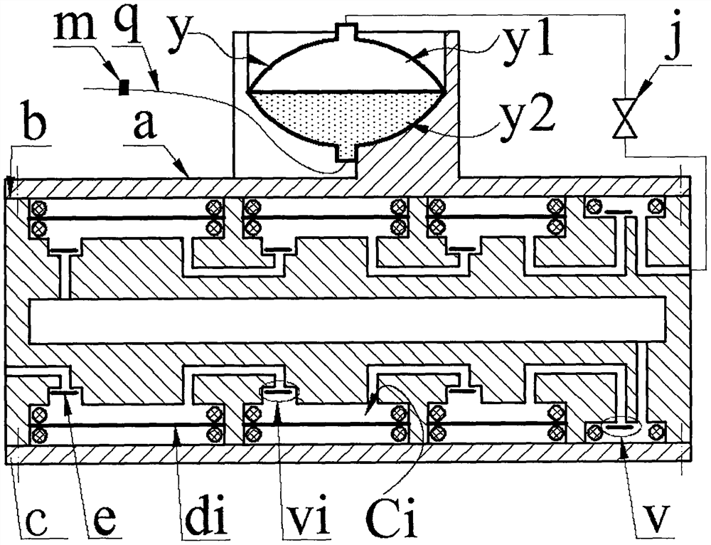
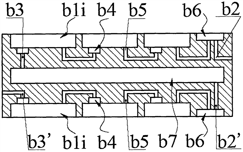
[0013] The middle part of the box b is equipped with a buffer cavity b7, the top is equipped with an upper inlet hole b3 and an upper outlet hole b2, the bottom is equipped with a lower inlet hole b3' and a lower outlet hole b2', and the upper and lower sides of the box b are equipped with outlets. b6 and at least two body cavities b1i; the diameters of the body cavities b1i from the upper inlet b3 to the upper outlet b2 and the lower inlet b3' to the lower outlet b2' all decrease in turn, and the top wall or bottom wall of the body cavity b1i is provided with There is an inlet b4 and an air outlet b5; on the top of the box b, the inlet b4 of the body cavity b1i with the largest diameter communicates with the buffer chamber b7 through the upper inlet b3, and the air outlet b5 of the body cavity b1i with the smallest diameter passes through the outlet b6 and the upper outlet b2 Connected; at the bottom of the box b, the inlet b4 of the body cavity b1i with the largest diameter c...


PUM


Abstract

The invention relates to a step-by-step pressurized pneumatic infusion device, which belongs to the field of medical equipment. The box body is provided with a buffer cavity and upper and lower inlet and outlet holes, the upper and lower sides of the box body are provided with an outlet cavity and at least two body cavities whose diameters decrease in sequence from the inlet hole to the outlet hole, and the body cavity is provided with an inlet cavity and an air outlet; The inlet and outlet chambers and the valve plates in them constitute the inlet and outlet valves respectively; the upper cover and the bottom plate are installed on the upper and lower sides of the box body, and the piezoelectric driver is crimped in each body cavity through the sealing ring to form a compression chamber; the upper inlet hole on the top of the box body, The compression chambers and outlet chambers are connected in series to form an upper compression unit, the lower inlet holes, compression chambers, outlet chambers and lower outlet holes at the bottom of the box are connected in series to form a lower compression unit, and the upper and lower compression units are connected in series through the buffer chamber; during operation, the upper and lower compression units are connected in series. The deformation directions of the two left and right adjacent drivers in the middle are opposite; the bladder cavity of the upper cover is equipped with an infusion bag with an air cavity and a medicine cavity, and the infusion tube of the medicine cavity is provided with a needle and a flow valve. Outlet connection.

Description

technical field [0001] The invention belongs to the field of medical equipment, and in particular relates to a step-by-step pressurized pneumatic infusion device. Background technique [0002] Injection mainly includes intravenous injection, intramuscular injection and subcutaneous injection. Intravenous injection is also called infusion drug administration. Most of the existing infusion devices are composed of infusion bottles, infusion tubes and infusion stands. This infusion mode will bring many problems in actual use: the flow rate is adjusted manually, and the flow control accuracy is not enough; the infusion bottle needs to be held high by others when the patient walks or goes to the toilet, which is inconvenient to move and the height of the infusion bottle is not high enough. Make the blood flow back; the patient or the nursing staff need to watch for a long time, if the infusion is not found in time, it may cause an accident; the liquid medicine is in contact with ...

Claims


Application Information

Patent Timeline
Patent Type & Authority Patents(China)
IPC IPC(8): A61M5/155A61M5/168
Inventor 阚君武吕鹏廖卫林万嫩王进程光明
Owner ZHEJIANG NORMAL UNIVERSITY
Why Eureka
Try Eureka