
Back auxiliary frame assembly of automobile

A rear sub-frame and assembly technology, applied in the field of sub-frame assembly and automobile rear sub-frame assembly, can solve the problems of low manufacturing cost, high fatigue life and material utilization rate, and no solution, and achieve cost Low, improve material utilization, simplify the effect of welding tooling

Inactive Publication Date: 2019-05-31
CHONGQING CHANGAN AUTOMOBILE CO LTD
View PDF7 Cites 1 Cited by
  • Summary
  • Abstract
  • Description
  • Claims
  • Application Information

AI Technical Summary

Problems solved by technology

The front beam is a hydroformed pipe fitting, which has a high fatigue life and material utilization rate, and low manufacturing cost; the cross section of the rear beam is a U-shaped flange structure, which can significantly improve the force on the edge of the part, improve the fatigue strength of the product, and avoid edge damage. Manufacturing defects cause stress concentration and lead to product failure; the structural design of the longitudinal beam takes into account the stability, handling and energy absorption of the vehicle, which can effectively protect the safety of the occupants and improve the collision safety of the vehicle, but it still has not been resolved. There are many deficiencies in the existing "well" shaped rear sub-frame assembly

Method used


Image

  • Back auxiliary frame assembly of automobile
  • Back auxiliary frame assembly of automobile
  • Back auxiliary frame assembly of automobile

Examples


Embodiment Construction

[0047] The present invention will be further described below in conjunction with the accompanying drawings and embodiments.

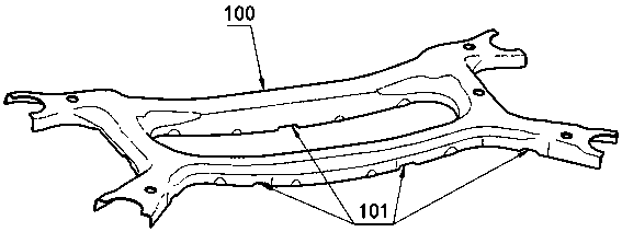
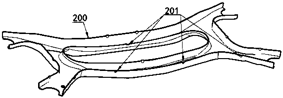
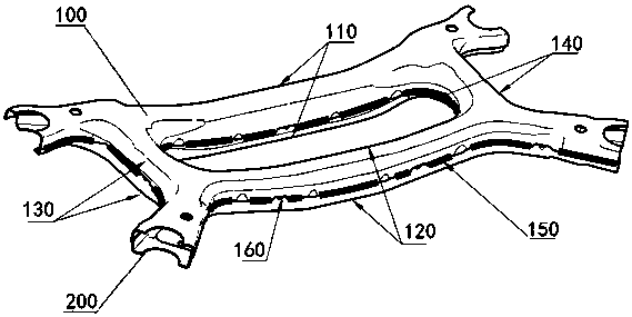
[0048] see Figure 1 to Figure 8 The shown rear sub-frame assembly of an automobile includes the rear sub-frame body, and the four corners of the rear sub-frame body are respectively provided with sleeves 300 for connecting the car body. Its outstanding substantive features are :

[0049] The rear sub-frame body is buckled by an upper plate 100 with an overall "well"-shaped partial section showing an inverted "U" and a lower plate 200 with a "well"-shaped partial section showing a "U" as a whole, and is fixedly connected by a weld 150 It is composed of a "well"-shaped cavity structure with a "mouth"-shaped section as a whole; the front part of the cavity structure is the front beam 110, the rear part is the rear beam 120, the left part is the left longitudinal beam 130, and the right part is the right longitudinal beam 140;

[0050] An upper swing ar...


PUM


Abstract

The invention relates to a back auxiliary frame assembly of an automobile. The back auxiliary frame assembly comprises a back auxiliary frame body, and sleeves used for being connected with an automobile body are respectively arranged at the four corners of the back auxiliary frame body; the back auxiliary frame body is composed of an upper plate with the whole body in a shape like the Chinese character of 'jing' and the local section in an inverted U shape and a lower plate with the whole body in a shape like the Chinese character of 'jing' and the local section in an inverted U shape, wherein the upper plate and the lower plate are in fixed fastening connection through welding seams, and the back auxiliary frame assembly with the whole body in a shape like the Chinese character of 'jing'and the local section in a shape like the Chinese character of 'kou' is of a cavity body structure; the front portion of the cavity body structure is a front transverse beam, the back portion of thecavity body structure is a back transverse beam, the left portion of the cavity body structure is a left longitudinal beam, and the right portion of the cavity body structure is a right longitudinal beam; upper swing arm installing brackets in inverted U shapes are respectively arranged on the left and right end portions of the front transverse beam; transverse U-shaped pulling rod installing brackets are respectively arranged under the left and right end portions of the front transverse beam; lower swing arm installing brackets are separately arranged under the middle of the back transverse beam. The strength and rigidity of the whole back auxiliary frame assembly can be improved, welding deformation is small, the size accuracy is higher, and stress distribution is uniform.

Description

technical field [0001] The invention relates to an automobile chassis, in particular to an automobile rear auxiliary frame assembly. In particular, it relates to a sub-frame assembly composed of a well-shaped upper plate and a well-shaped lower plate that are integrally stamped and formed by fastening and welding. Background technique [0002] The rear sub-frame assembly of the automobile mainly plays the role of supporting the components of the suspension system, transmitting the force of the chassis, increasing the rigidity, installing the control arm and guiding the movement trajectory. In order to meet the layout and performance of the multi-link suspension, the "well"-shaped rear sub-frame assembly is generally used, which includes the front beam, rear beam, left longitudinal beam, right longitudinal beam, and the upper and lower control arms. It is arranged on the "well" beam of the auxiliary frame, and the front and rear four corners of the "well" beam are provided w...

Claims


Application Information

Patent Timeline
IPC IPC(8): B62D21/02B62D21/11
Inventor 孙勇石明祥乔斌董泽李海史广才邓庆波杨文荣
Owner CHONGQING CHANGAN AUTOMOBILE CO LTD
Learn More