
Method for manufacturing 3D glass

A production method and glass technology, applied in glass manufacturing equipment, glass production, glass molding, etc., can solve the problems of increased processing cost, reduced mold surface life, unqualified 3D glass size, etc., to reduce mold wear and development. Difficulty, the effect of avoiding frictional contact

Inactive Publication Date: 2019-05-31
TOMI CHENGDU APPLIED TECH RES INST CO LTD
View PDF0 Cites 14 Cited by
  • Summary
  • Abstract
  • Description
  • Claims
  • Application Information

AI Technical Summary

Problems solved by technology

[0008] 1. Low yield rate
[0009] During thermocompression molding, the 2D glass will be unqualified in size due to the offset of the placement position or uneven molding pressure in the mold, such as the unequal arc height on the left and right sides
[0010] 2. The mold imprint is heavy and the grinding cost is high
[0011] Because both the convex mold and the concave mold are in contact with the glass surface during the forming process, resulting in mold impressions on the convex and concave surfaces, resulting in 35 minutes of grinding for the convex surface of the glass and 55 minutes for the concave surface, which increases the processing cost
[0012] 3. Low mold life and high production cost
[0013] During molding, the molds are pressed and rubbed against each other, resulting in a reduction in the life of the mold surface, and easy-to-fall dust particles adhere to the glass surface, forming pitting and other irreparable defects
[0014] 4. It is difficult to develop new products such as large angles
[0016] 5. Long new product development cycle
[0017] Existing technical solutions: According to the size of 3D glass and thermoforming analysis, reversely deduce the dimension of the expanded 2D glass, then make a mold, perform a forming test, and correct the size of the 2D glass after testing. Generally, it will go through 3-5 repeated corrections. In the process of mold processing, trial molding, and testing, the development cycle is long

Method used


Image

  • Method for manufacturing 3D glass
  • Method for manufacturing 3D glass
  • Method for manufacturing 3D glass

Examples


Embodiment Construction

[0049] In order to make the object, technical solution and advantages of the present invention clearer, the present invention will be further described in detail below in conjunction with the accompanying drawings and embodiments. It should be understood that the specific embodiments described here are only used to explain the present invention, and are not intended to limit the present invention, that is, the described embodiments are only some of the embodiments of the present invention, but not all of the embodiments. The components of the embodiments of the invention generally described and illustrated in the figures herein may be arranged and designed in a variety of different configurations. Accordingly, the following detailed description of the embodiments of the invention provided in the accompanying drawings is not intended to limit the scope of the claimed invention, but merely represents selected embodiments of the invention. Based on the embodiments of the present ...


PUM


Abstract

The invention discloses a method for manufacturing 3D glass, which comprises the following steps: step 1, cutting a large glass base material into small pieces of glass with preset sizes; step 2, placing the small pieces of glass in a mold, bending and adhering the small pieces of glass on a concave surface of the mold by vacuum adsorption at a glass hot bending temperature after the small piecesof glass are softened to form a 3D glass blank; step 3, performing laser cutting on the 3D glass blank to form a 3D glass semi-finished product; step 4, performing CNC polishing and chamfering on the3D glass semi-finished product to obtain the 3D glass; step 5, performing sweeping treatment on the surface of the 3D glass.According to the method for manufacturing the 3D glass, the required 3D glass appearance is directly formed by forming the glass with reserved processing allowance and laser cutting the appearance after forming, so that the development process of reverse derivation and repeated tests is avoided, the development difficulty of large-angle new products is reduced, the development period is shortened, the product yield is improved, and the cost is reduced.

Description

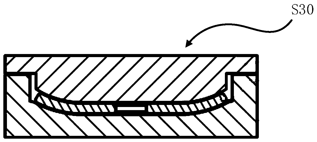
technical field [0001] The invention relates to the technical field of electronic equipment, in particular to a method for manufacturing 3D glass. Background technique [0002] With the rapid development of electronic devices, in order to improve the aesthetics of electronic devices, 3D glass is used more and more. Most of the existing 3D glass production methods are as Figure 1-4 shown, including the following steps: [0003] Step S10, material cutting: cutting the large glass base material into small square glass pieces of preset size. [0004] Step S20, CNC engraving: the shape, hole, and chamfering of the square glass are processed by the engraving machine to form 2D glass with high-precision dimensions. [0005] Step S30, hot press molding: accurately put the 2D glass into the groove of the mold, the mold has at least a convex mold and a concave mold, the mold is heated to 700-750°C by the molding machine at high temperature, and after the glass plate is softened, th...

Claims


Application Information

Patent Timeline
IPC IPC(8): C03B21/04C03B23/035C03B33/08B24B1/00
CPCB24B1/00C03B21/04C03B23/0352C03B33/082Y02P40/57
Inventor 张锡强汤金慧王京岱
Owner TOMI CHENGDU APPLIED TECH RES INST CO LTD
Learn More