Belt-load testing device used by a clutch electronic control pneumatic separating mechanism

A technology of pneumatic separation and testing device, which is used in the testing of machine/structural components, measuring devices, clutches, etc.

Pending Publication Date: 2019-05-31
BIT INTELLIGENT VEHICLE TECH CO LTD
View PDF0 Cites 2 Cited by
  • Summary
  • Abstract
  • Description
  • Claims
  • Application Information

AI Technical Summary

Problems solved by technology

At present, vehicles such as passenger cars and logistics vehicles mostly use two types of clutch pneumatic separation mechanisms, pneumatic control and hydraulic control. The hydraulic control requires a liquid source on the vehicle, takes up a lot of space, has many systems, the liquid is easy to pollute the environment, and has high costs. How to combine the existing power supply and air source on the vehicle to realize the clutch electric control pneumatic separation structure

Method used


Image

  • Belt-load testing device used by a clutch electronic control pneumatic separating mechanism
  • Belt-load testing device used by a clutch electronic control pneumatic separating mechanism
  • Belt-load testing device used by a clutch electronic control pneumatic separating mechanism

Examples


Embodiment 1

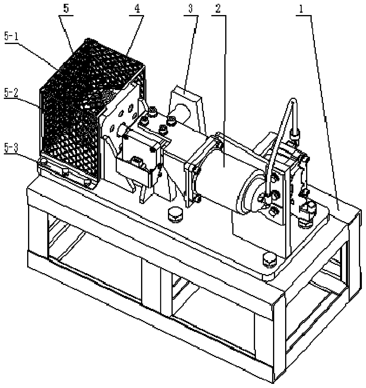
[0053] Such as figure 1 As shown, the on-load test device used by an electronically controlled pneumatic separation mechanism proposed by the present invention includes a base 1, an electronically controlled pneumatic separation mechanism 2, a support frame 3, and a disc mechanism 4;

[0054] The electro-pneumatic separation mechanism 2 includes a solenoid valve 2-1, an air pipe 2-2, a booster cylinder 2-3, and a combination bracket 2-4. The solenoid valve 2-1 is located on the side of the booster cylinder 2-3, and the side of the booster cylinder 2-3 The center line is consistent with the center line of the combined bracket 2-4;

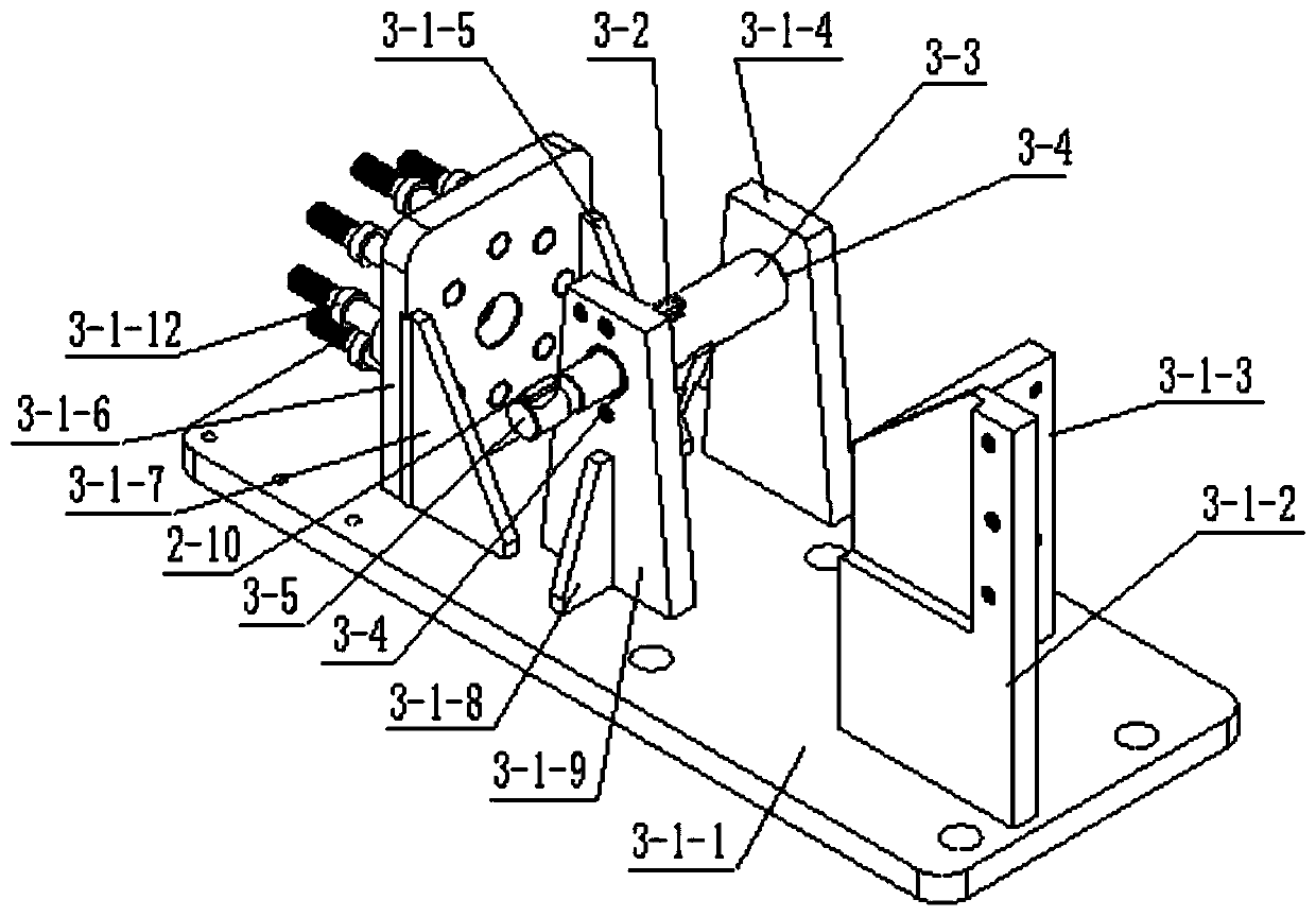
[0055] The support frame is located on the base, and an L-shaped support, a rotating shaft support frame, and a disc mechanism fixing plate 3-1-6 are sequentially arranged from one side of the base, and the axis of the rotating shaft support frame is perpendicular to the center line of the booster cylinder 2-3. The centerline of the fixed disk 3-1-...

Embodiment 2

[0067] Such as figure 1 As shown, the present invention proposes a load test device for an electropneumatic separation mechanism, which includes a base 1 , an electropneumatic separation mechanism 2 , a support frame 3 , a disc mechanism 4 , and a shield assembly 5 . The support frame 3 of the load testing device is seated on the base 1, the longitudinal long side of the support frame 3 is parallel to the longitudinal long side of the base 1, and the center line of the booster cylinder of the electro-pneumatic separation mechanism 2 is vertically longer than the support frame 3. The sides are parallel, perpendicular to the axis of the rotating shaft of the support frame 3, extending to the right above the front of the rotating shaft, and the center line of symmetry of the disc mechanism 4 is perpendicular to the axis of the rotating shaft on the support frame 3, and is located in the left front; the electric control pneumatic separation The swing arm of the mechanism 2 is inse...


PUM


Abstract

The invention discloses a belt-load testing device used by a clutch electronic control pneumatic separating mechanism. The electromagnetic valve is located on the side surface of the power assisting cylinder, the center line of the power assisting cylinder is consistent with the center line of the combined support, the supporting frame is located on the base, an l-shaped bracket, a rotating shaftsupporting frame and a disc type mechanism fixing disc are sequentially arranged on one side of the base from one side of the base, the axis of the rotating shaft supporting frame is perpendicular tothe center line of the power assisting cylinder, the center line of the fixed disc of the disc-type mechanism is consistent with the center line of the combined bracket, the central line of the largehole in the fixed disc is consistent with the symmetric line of the thickness of the pull arm, the two sides of the l-shaped supporting frame are respectively provided with a special-shaped support and an electromagnetic valve of the power-assisted cylinder, the rotating shaft of the rotating shaft supporting frame penetrates through the front T-shaped bracket on one side in sequence, and the special-shaped support forms a rotary shaft end face shaft and is connected with a swing arm of the pneumatic separation mechanism. The loading testing device is used for the electric control pneumatic separating mechanism, so that the on-off of the electromagnetic valve is realized, and the test function of the on-off gas of the power-assisted cylinder is controlled.

Description

technical field [0001] The invention relates to a clutch electro-pneumatic separation mechanism of an AMT control system—executive mechanism, in particular to related technical indicators and a load-carrying function test of the clutch electro-pneumatic separation mechanism. Background technique [0002] The electro-pneumatic separation mechanism is a separation mechanism that works by electrically controlling the cylinder to provide kinetic energy to the clutch. It can be applied to vehicles such as mechanical power transmission, hybrid power transmission, passenger cars and logistics vehicles. At present, vehicles such as passenger cars and logistics vehicles mostly use two types of clutch pneumatic separation mechanisms, pneumatic control and hydraulic control. Hydraulic control requires a liquid source on the vehicle, takes up a lot of space, has many systems, the liquid is easy to pollute the environment, and has high costs. How to combine the existing power supply and ...

Claims


Application Information

Patent Timeline
IPC IPC(8): F16D48/06F16D48/02G01M99/00
Inventor 刘颖胡宇辉彭建鑫张瑞捷
Owner BIT INTELLIGENT VEHICLE TECH CO LTD
Why Eureka
Try Eureka