System for eliminating fiber-optic gyroscope dead zone

A technology of fiber optic gyroscope and dead zone, which is applied in the direction of Sagnac effect gyroscope, etc., can solve the problem that the dead zone index of the fiber optic gyroscope is not up to standard, and achieve the effect of saving resources, facilitating mass production, and improving the first-time yield

Inactive Publication Date: 2019-05-31
BEIJING INST OF COMP TECH & APPL
View PDF5 Cites 3 Cited by
  • Summary
  • Abstract
  • Description
  • Claims
  • Application Information

AI Technical Summary

Problems solved by technology

[0005] The purpose of the present invention is to provide a system for eliminating the dead zone of the fiber optic gyroscope, which is used to solve the problem that the dead zone caused by the crosstalk of the fiber optic gyroscope detection circuit board causes the dead zone indicator of the fiber optic gyroscope to fail to meet the standard.

Method used


Image

  • System for eliminating fiber-optic gyroscope dead zone
  • System for eliminating fiber-optic gyroscope dead zone
  • System for eliminating fiber-optic gyroscope dead zone

Examples


Embodiment Construction

[0019] In order to make the purpose, content, and advantages of the present invention clearer, below in conjunction with accompanying drawing and embodiment, the specific embodiment of the present invention is described in further detail.

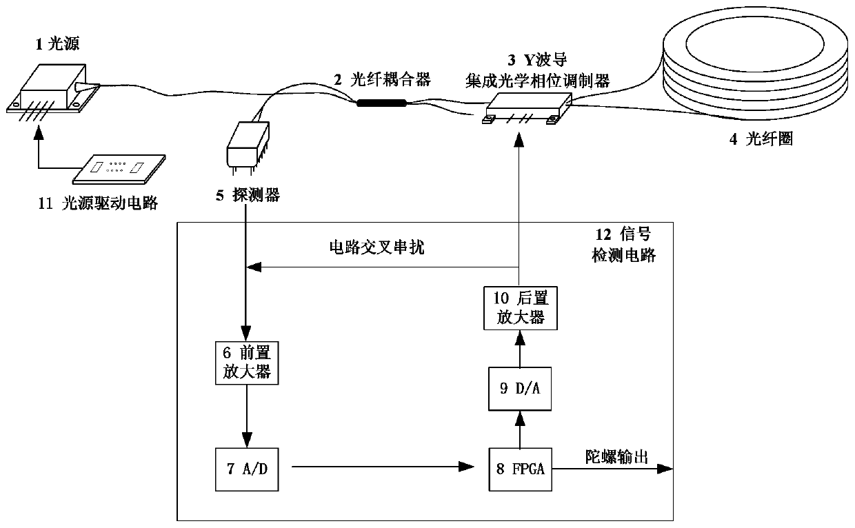
[0020] figure 1 The schematic diagram of the crosstalk structure of the optical fiber gyroscope circuit is shown, such as figure 1 As shown, the composition of the fiber optic gyroscope mainly includes a light source 1, a fiber ring 4, a fiber coupler 2, a Y waveguide 3, a photoelectric detector 5 and a signal detection circuit 12. The light source 1 is connected to the fiber coupler 2, the fiber coupler 2 is connected to the detector 5, and the fiber coupler 2 is connected to the Y waveguide 3. The Y waveguide 3 is connected to the fiber ring 4 . The detector 5 is connected to the input of the signal detection circuit 12 . One output of the signal detection circuit is connected to the Y waveguide, and the other output is used as the out...


PUM


Abstract

The invention relates to a system for eliminating a fiber-optic gyroscope dead zone, and the system is characterized in that one output of a signal detection circuit is connected with a Y waveguide, and the other output of the signal detection circuit is used as a gyroscope output signal; the signal detection circuit comprises a pre-amplifier, an A / D circuit, an FPGA, a D / A circuit and a post-amplifier; the output of the post-amplifier is transmitted to the pre-amplifier and the Y waveguide; the FPGA outputs a gyroscope output signal and outputs a feedback signal to the D / A circuit; in the closed-loop process of the FPGA, a compensation phase shift is added, and the introduced compensation phase shift needs to be greater than a peak-to-peak value of the equivalent phase shift caused by crosstalk, and the compensation phase shift does not bring additional output to the gyroscope. The problem of the one-time yield of the fiber-optic gyroscope caused by the dead zone of a signal detectioncircuit board is solved.

Description

technical field [0001] The invention relates to a system for eliminating the dead zone of an optical fiber gyroscope, in particular to a system for eliminating the dead zone of an interference-type closed-loop optical fiber gyroscope. Background technique [0002] Fiber optic gyroscope is an important component of inertial technology. Compared with traditional mechanical gyroscopes, fiber optic gyroscopes have no high-speed rotating mechanical rotors, are not sensitive to acceleration, and have the advantages of small size, low power consumption, and long life. And navigation and other fields have broad application prospects. In recent years, fiber optic gyroscopes have been rapidly developed in some universities, research institutes and companies. With the deepening of research, the requirements for the accuracy and stability of fiber optic gyroscopes have also increased. [0003] The closed-loop fiber optic gyroscope has the advantages of large dynamic range and good sca...

Claims


Application Information

Patent Timeline
IPC IPC(8): G01C19/72
Inventor 李妍
Owner BEIJING INST OF COMP TECH & APPL
Why Eureka
Try Eureka