A detection device for food inspection
A detection device and food inspection technology, which is applied in the direction of material inspection, food testing, etc., can solve the problems of complicated operation, affecting the accuracy of food detection, time-consuming and labor-intensive, etc.
- Summary
- Abstract
- Description
- Claims
- Application Information
AI Technical Summary
Problems solved by technology
Method used
Image
Examples
Embodiment 1
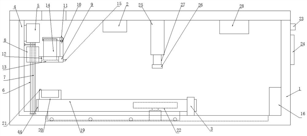
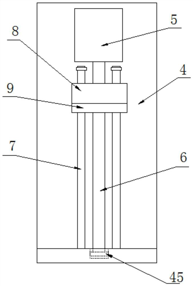
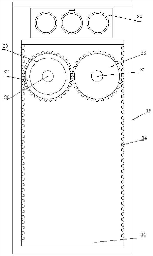
[0029] like Figure 1-7As shown, the detection device for food inspection according to the embodiment of the present invention includes a detection box body 1, the detection box body 1 is a cavity structure with an open top, and the inner top side of the detection box body 1 is provided with The controller 2 and the movable mechanism 25 positioned at one side of the controller 2, the bottom end of the movable mechanism 25 is provided with a movable rod 27, and the bottom end of the movable rod 27 is provided with a detection probe 26, and the detection box body 1 is provided with a cooling fan 28 on one side of the movable mechanism 25, and the bottom end of the detection box body 1 is provided with a limit seat 3 and a printer 16 located on one side of the limit seat 3. One side of the body 1 is provided with a moving mechanism, and the moving mechanism includes a support plate 4 arranged on one side of the inner wall of the detection box body 1, and a motor-5 is provided at ...
Embodiment 2
[0032] like figure 1 , 3 As shown, the support plate 4 has an L-shaped structure, the movable plate 19 has a rectangular structure, and the seating base 20 is provided with a plurality of placement slots matching the detection placement box 14 . By setting the support plate 4 of the L-shaped structure, the stability of the support plate 4 is effectively improved, and then by setting several placement grooves on the placement seat 20, it is convenient to place a plurality of detection placement boxes 14 in the placement grooves, and then Perform a synchronization check.
[0033] like figure 1 , 4 As shown, the bottom end of the movable column 35 is provided with several rolling beads 36 . The frictional force between the movable column 35 and the movable groove 37 is effectively reduced by setting several rolling balls 36 .
[0034] like figure 1 , 2 As shown, the bottom end of the screw rod 6 extends into the groove on the L-shaped step of the support plate 4 , and the ...
Embodiment 3
[0038] like Figure 7 As shown, the movable mechanism 25 includes a mounting plate 46 arranged at the top inside the detection box body 1, and the bottom end of the mounting plate 46 is provided with a slide rail 47 and a storage box positioned at one side of the slide rail 47. 48, the bottom of the slide rail 47 is provided with a placement box 2 49, the inside of the placement box 1 48 is provided with a motor 4 50, and the output shaft of the motor 4 50 is provided with a motor located below the placement box 1 48 Rotating disk 51, the bottom end side of described rotating disk 51 is provided with rotating rod 52, and described rotating rod 52 is sleeved with the pull bar 53 that is connected with described placement box two 49 sidewall bottoms, and described placement box two The two sides of the top of 49 are symmetrically provided with moving assemblies flexibly connected with the slide rail 47, and the inside of the placement box 49 is provided with a cylinder 54, and t...
PUM
 Abstract
Description
Claims
Application Information
 - R&D
- Intellectual Property
- Life Sciences
- Materials
- Tech Scout
- Unparalleled Data Quality
- Higher Quality Content
- 60% Fewer Hallucinations
Browse by: Latest US Patents, China's latest patents, Technical Efficacy Thesaurus, Application Domain, Technology Topic, Popular Technical Reports.
© 2025 PatSnap. All rights reserved.Legal|Privacy policy|Modern Slavery Act Transparency Statement|Sitemap|About US| Contact US: help@patsnap.com


