Oil pressure braking system for rail transit vehicle and control method thereof

A rail transit vehicle, hydraulic braking technology, applied in the direction of brakes, vehicle components, brake transmissions, etc., can solve the problems of liquid leakage, damage to compression components, increase the braking distance, etc., to reduce material and noise emissions , reduce work intensity and cost, and reduce the consumption of friction materials

Pending Publication Date: 2019-06-04
CRRC CHANGZHOU TECH MARK IND CO LTD +1
View PDF6 Cites 4 Cited by
  • Summary
  • Abstract
  • Description
  • Claims
  • Application Information

AI Technical Summary

Problems solved by technology

This patent has the following problems: only the air compressor operates during actual braking, there is no energy storage device, and the gas or liquid can only flow in the compressor cavity
For the gaseous medium that is easier to compress, although the air compressor can operate, the braking force provided by the brake will fluctuate greatly due to the different compression process of the compressor on the gas; for the liquid medium that is difficult to compress , Instantaneous compression will lead to a sharp increase in liquid pressure, which can easily cause damage to the compression element and cause liquid leakage. The fluctuation of the vehicle will cause uneven deceleration of the vehicle, the vehicle will move back and forth, and even the vehicle will stop suddenly due to the inability to continue to compress the liquid, which will have a great impact on the comfort and safety of the vehicle.
Due to the different vehicle speeds, the speed of the air compressor

Method used


Image

  • Oil pressure braking system for rail transit vehicle and control method thereof
  • Oil pressure braking system for rail transit vehicle and control method thereof
  • Oil pressure braking system for rail transit vehicle and control method thereof

Examples


Embodiment 1

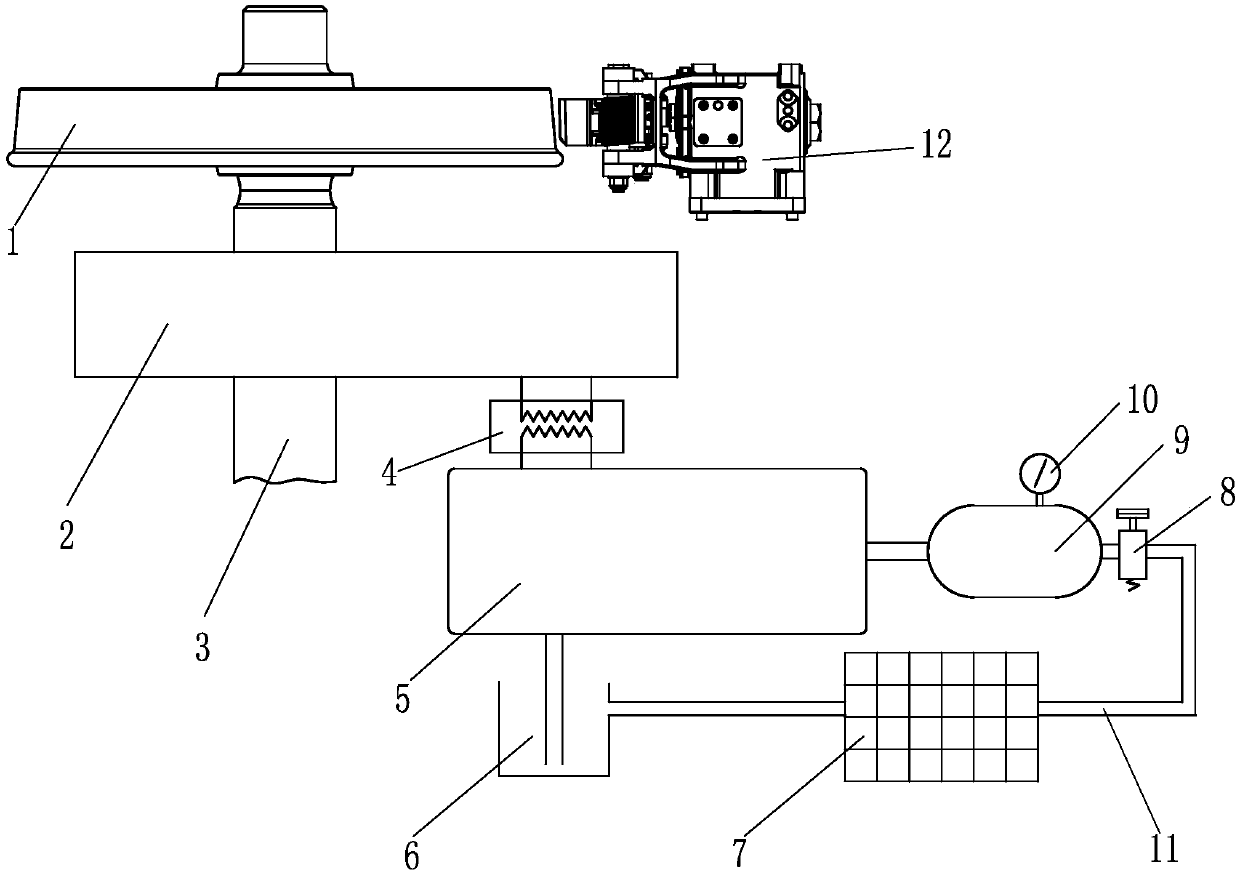
[0020] See figure 1 and figure 2 , this embodiment includes a gear box 2, an axle 3, a hydraulic pump 5, a pressure monitoring assembly 10 for monitoring the pressure in the high-pressure oil tank 9, and a mechanical braking device 12. Wheel 1 is installed on the axle 3. The axle 3 passes through the gearbox 2, and the axle 3 is used as the power input shaft of the gearbox 2. The output shaft of the gearbox 2 and the main shaft of the hydraulic pump 5 are connected by a clutch device 4. The input oil pipe of the hydraulic pump 5 is connected to the oil storage box 6 Connection, the output oil pipe of the hydraulic pump 5 is connected with the input end of the high pressure oil tank 9, the output end of the high pressure oil tank 9 is connected with the oil storage box 6 by a pressure relief oil pipe 11, and an electric control switch is connected in series on the pressure relief oil pipe 11 8. A radiator 7 is connected in series between the electric control switch 8 and the...


PUM


Abstract

The invention discloses an oil pressure braking system for a rail transit vehicle. The system includes an axle, a gear box and a hydraulic pump; the axle penetrates through the gear box to serve as power input of the gear box; an output shaft of the gear box is connected with a main shaft of the hydraulic pump through a clutch device, an input oil pipe of the hydraulic pump is connected with an oil storage box, an output oil pipe of the hydraulic pump is connected with the input end of a high-pressure oil tank, the output end of the high-pressure oil tank is connected with the oil storage boxthrough a pressure relief oil pipe, and an electric control switch is connected to the pressure relief oil pipe in series. High-speed braking is achieved through oil pressure braking, real-time monitoring and adjusting can be conducted, it is guaranteed that a vehicle conducts braking according to the needed braking deceleration, braking force and braking deceleration are stable and reliable, riding comfort is high, and the system can adapt to both high-speed braking and low-speed braking.

Description

technical field [0001] The invention relates to an oil pressure brake system for a rail transit vehicle and a control method thereof. Background technique [0002] The braking device of rail transit vehicles is an important guarantee for the safe operation of vehicles. The common braking methods of rail transit vehicles mainly include mechanical braking and electric braking. Electric braking can only be realized on motor vehicles with drive systems, while mechanical brakes are installed on trailers. Mechanical brakes convert the kinetic energy of the vehicle into heat energy through the friction of the friction pair to generate braking effect, so there will be friction Auxiliary loss requires regular replacement of the friction pair, and it will generate a lot of noise and dust pollution during use. When braking at high speed, a large amount of heat energy will be generated, which will reduce the service life of the friction material and bring further speed-up to rail trans...

Claims


Application Information

Patent Timeline
IPC IPC(8): B60T13/132
CPCY02T30/00
Inventor 金璟吴波王子晨伍安旭冯畅谭久才曹益民张宇宸
Owner CRRC CHANGZHOU TECH MARK IND CO LTD
Why Eureka
Try Eureka