Saccharification machine for microbial fermentation

A technology for microbial fermentation and fermenter, which is applied in bioreactor/fermenter combination, biochemical cleaning device, bioreactor/fermenter for specific purposes, etc. The problem of long microbial fermentation time, etc., can achieve the effect of increasing the fermentation time, improving the saccharification effect, and increasing the amount of dissolved oxygen.

Pending Publication Date: 2019-06-04
TIBET RENBU DAREWA QINGKE WINE
View PDF0 Cites 5 Cited by
  • Summary
  • Abstract
  • Description
  • Claims
  • Application Information

AI Technical Summary

Problems solved by technology

When the existing saccharification and fermentation equipment adopts microbial fermentation, it needs to pass oxygen to the inside of the equipment. The existing saccharification machine includes a fermenter and is equipped with an air supply device inside. However, with the existing equipment, the oxygen enters through the bottom, and the stirring Under low conditions, the oxygen removal speed is fast, the dissolved oxygen rate is not high, the microbial fermentation time is long, and the saccharification effect is not good

Method used


Image

  • Saccharification machine for microbial fermentation
  • Saccharification machine for microbial fermentation
  • Saccharification machine for microbial fermentation

Examples


Embodiment 1

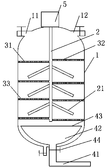
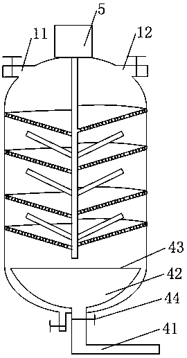
[0020] Such as figure 1 , 3 The shown saccharification machine for microbial fermentation includes a fermenter 1, a stirring bar 2 coaxially arranged with the fermenter 1, and an air outlet 11 arranged on the fermenter 1, which is the same as the existing structure, and the fermenter is also provided with a The feed port 12, the feed port, and the bottom of the fermenter 1 are provided with an air delivery device. The fermenter 1 is provided with a multi-layer partition, and the partition includes a first fan-shaped plate 31 and a second fan-shaped plate 32. The larger arc edge of the first fan-shaped plate 31 is fixed on the inner wall of the fermenter 1 and the smaller The arc edge is attached to the stirring rod 2, the smaller arc edge of the second fan-shaped plate 32 is fixed on the stirring rod 2 and the larger arc edge is attached to the inner wall of the fermentation tank 1, and the rotation of the stirring rod can drive the second fan-shaped plate 32 to rotate , the...

Embodiment 2

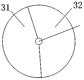
[0022] This embodiment optimizes the first fan-shaped plate 31 and the second fan-shaped plate 32 on the basis of the structure of the above-mentioned embodiment, that is, as figure 2 As shown, both the first fan-shaped plate 31 and the second fan-shaped plate 32 are arranged perpendicular to the stirring rod, but this structure is not convenient for cleaning the fermenter 1 .

[0023] can also be used as figure 2 In the structure shown, the height of the larger arc side of the first fan-shaped plate 31 and the second fan-shaped plate 32 is higher than the height of the smaller arc side, that is, there is a certain angle between the first fan-shaped plate 31 and the horizontal plane. Preferably, the included angle between the first fan-shaped plate 31 and the stirring rod 2 is greater than 40 degrees and less than 80 degrees. The angle between the first fan-shaped plate 31 and the stirring rod 2 is 60 degrees. Preferably, the length of the larger arc side of the first fan-...

Embodiment 3

[0025] This embodiment has been optimized on the basis of the structure of the above-mentioned embodiment, that is, the stirring blade 21 can also be fixed on the stirring rod 2, and the stirring blade 21 is placed between the adjacent two-layer partitions and the stirring blade 21 is connected to the first fan-shaped plate. 31 are not parallel.

[0026] The air supply device comprises an air supply pipe 41, a buffer chamber 42 communicated with the air supply pipe 41, and an air uniform plate 41 arranged on the top surface of the buffer chamber 42. The air supply pipe 41 is provided with a one-way valve 44, and the air uniform plate 43 is Provided with vent holes.


PUM

PropertyMeasurementUnit
diameteraaaaaaaaaa

Abstract

The invention discloses a saccharification machine for microbial fermentation. The machine comprises a fermentation tank, a stirring rod and an air outlet arranged on the fermentation tank, an air supply device is arranged at the bottom of the fermentation tank, multilayer partition plates are arranged in the fermentation tank, each partition plate comprises a first sector plate and a second sector plate, the larger arc edge of the first sector plate is fixed on the inner wall of the fermentation tank and the smaller arc edge fits the stirring rod, the smaller arc edge of the second sector plate is fixed on the stirring rod and the larger arc edge fits the inner wall of the fermentation tank, air holes are formed in the first sector plate and the second sector plate, the first sector plateis arranged below the second sector plate and the two sector plates fit each other, and the total length of the larger arc edges of the first sector plate and the second sector plate is the same as the circumference of the inner wall of the fermentation tank. The multilayer partition plates are provided and have a function of obstructing the gas flow speed. While inputting oxygen with the same volume, the air supply device can greatly improve the dissolved oxygen in the fermentation tank, improve the fermentation time of microorganisms, and improve the saccharification effect.

Description

technical field [0001] The invention relates to the field of microbial fermentation tanks, in particular to a saccharification machine for microbial fermentation. Background technique [0002] Saccharification refers to the process of decomposing starch into sweet products by adding water. It is the main process of starch sugar manufacturing process and the main process of many intermediate products in the food fermentation process. When the existing saccharification and fermentation equipment adopts microbial fermentation, it needs to pass oxygen to the inside of the equipment. The existing saccharification machine includes a fermenter and is equipped with an air supply device inside. However, with the existing equipment, the oxygen enters through the bottom, and the stirring Under low conditions, the oxygen removal speed is fast, the dissolved oxygen rate is not high, the microbial fermentation time is long, and the saccharification effect is not good. Contents of the in...

Claims


Application Information

Patent Timeline
Patent Type & Authority Applications(China)
IPC IPC(8): C12M1/40C12M1/04
Inventor 拉琼赵建平
Owner TIBET RENBU DAREWA QINGKE WINE
Why Eureka
Try Eureka