
Ductile coupling beam swinging steel frame system

A technology of steel frame and connecting beams, which is applied in basic structure engineering, building components, earthquake resistance, etc., can solve the problems of difficult control, serious component damage, large residual deformation, etc., and achieve clear action mechanism, guaranteed use function and simple structure Effect

Active Publication Date: 2019-06-04
DALIAN UNIV OF TECH
View PDF3 Cites 9 Cited by
  • Summary
  • Abstract
  • Description
  • Claims
  • Application Information

AI Technical Summary

Problems solved by technology

[0003] It is difficult to control the damage mode and energy-dissipating parts of the existing steel frame structure system under earthquake action, and it is difficult to guarantee the overall failure mode of "strong column and weak beam", and the post-disaster component damage is serious, the residual deformation is large, and it is difficult to repair

Method used


Image

  • Ductile coupling beam swinging steel frame system
  • Ductile coupling beam swinging steel frame system
  • Ductile coupling beam swinging steel frame system

Examples


Embodiment 1

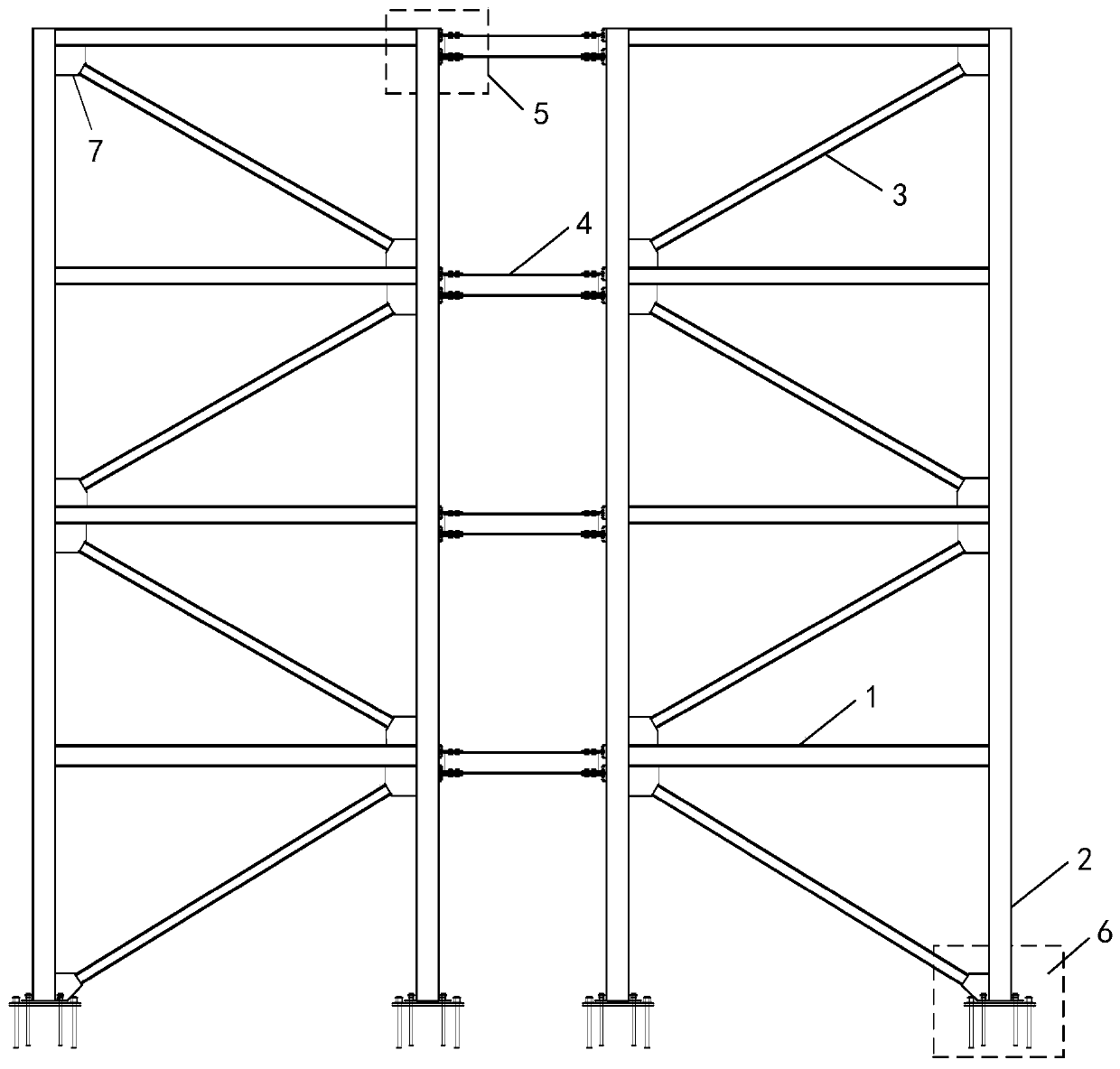
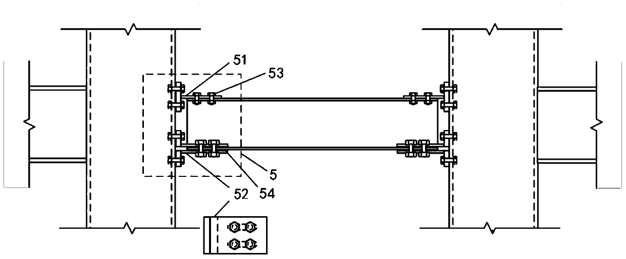
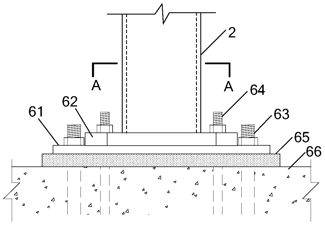
[0026] Embodiment 1: As shown in the figure, the present invention is a swinging steel frame structure system with ductile coupling beams, which mainly consists of frame beams 1, frame columns 2, steel supports 3, replaceable coupling beams 4, and energy-dissipating beam-column nodes 5 And swing type column foot 6 forms. Frame beam 1, frame column 2 and steel support 3 form a steel support frame, and steel support 3 is installed at the inner diagonal position of the steel support frame on both sides of each floor, and the steel support frames on the left and right sides are connected by replaceable connecting beam 4 , the replaceable connecting beam 4 is connected to the frame column 2 through the energy-dissipating beam-column node 5, and the bottom of the frame column 2 adopts a swing-type column foot 6.

[0027] The frame beam 1 is in the form of a steel member such as an I-shaped cross section or a square steel pipe cross section.

[0028] The frame column 2 is in the cro...


PUM


Abstract

The invention belongs to the technical field of civil engineering aseismic structural systems, and provides a ductile coupling beam swinging steel frame system. According to the ductile coupling beamswinging steel frame system, steel supporting frames composed of frame beams, frame columns and steel supports bear the vertical load, the lateral rigidity and resilience are provided, and the elasticity is maintained all the time by allowing the bottoms of the steel columns to rise under the action of an earthquake; seismic energy is dissipated through replaceable connecting beams and swinging type column feet, wherein the steel supporting frames on the left side and right side are connected through the replaceable connecting beams, and the bottoms of the frame columns adopt the swinging typecolumn feet; when a structural system is subjected to the seismic action, the seismic energy is dissipated by the replaceable connecting beams and the swinging type column feet, and the steel supporting frames on the two sides are prevented from being damaged; and the concept of the structural system is clear, design is simple, the action mechanism is clear, the replaceable connecting beams and the swinging type column feet are used as energy dissipation elements and connected with steel columns through bolts, input energy is dissipated in the earthquake, and after the earthquake, the purposeof quick recovery of the use function of the structure system can be achieved by replacing an energy dissipator.

Description

technical field [0001] The invention belongs to the technical field of anti-seismic structural systems of civil engineering, and in particular relates to a swinging steel frame structure system of ductile coupling beams. Background technique [0002] In recent years, some areas of the earth have entered an active period of earthquakes, and earthquakes with large magnitudes have occurred in many places around the world. The new trend of earthquake damage is that the economic losses caused by disasters are extremely large, and the huge reconstruction and repair costs after disasters occur. This makes "resilient disaster prevention" a new trend in disaster prevention research. Resilience-oriented disaster prevention design aims to reduce earthquake losses and recovery time by improving the disaster prevention capability of engineering structures or controlling the difficulty of recovery from disasters in engineering structures. [0003] It is difficult to control the damage mo...

Claims


Application Information

Patent Timeline
Patent Type & Authority Applications(China)
IPC IPC(8): E04B1/24E04B1/58E04B1/98E04H9/02E02D27/42
Inventor 崔瑶王枫智李浩刘洪滔
Owner DALIAN UNIV OF TECH
Learn More