Heat pipe type heating device

A heating device, heat pipe type technology, applied in the direction of heating devices, lighting and heating equipment, progressive dryers, etc., can solve the problems of slow drying rate of materials, incapable of heat conduction and heat exchange, complex internal structure of heating plate, etc., to achieve increased Heat conduction effect, effect of increasing circulation speed

Inactive Publication Date: 2019-06-04
MENGZHOU YUANHONG DRYING EQUIP RES & DEV CO LTD
View PDF0 Cites 1 Cited by
  • Summary
  • Abstract
  • Description
  • Claims
  • Application Information

AI Technical Summary

Problems solved by technology

When the heat conduction medium (water, heat transfer oil) in the heating plate of the belt dryer flows and conducts heat in the heating plate for a long time, scale and oil will form on the plate inside the heating plate. The internal structure of the heating plate is complicated, and the internal structure of the heating plate The scale and oil on the plate body is not easy to clean and descale, and the heating plate with scale and oil will affect the conduction and heat transfer of heat energy
[0003] The lower heating plate of the belt dryer is installed under the upper conveyor belt. The heat conduction of the lower heating plate (the mate

Method used


Image

  • Heat pipe type heating device
  • Heat pipe type heating device
  • Heat pipe type heating device

Examples


Embodiment Construction

[0099] Below in conjunction with accompanying drawing, the present invention will be further described:

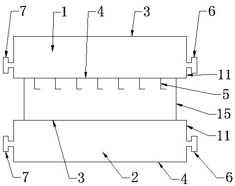
[0100] Such as figure 1 , figure 2 , Figure 4 A heat pipe type heating device shown includes an upper heating plate 1 , a lower heating plate 2 , a support 15 , and a stirring device 5 .

[0101] The upper heating plate 1 and the lower heating plate 2 are supported and fixed by a bracket 15 .

[0102] The only difference in the composition structure of the upper heating plate 1 and the lower heating plate 2 is that the bottom plate 4 is different.

[0103] According to the different needs of heating, the bottom plate 4 of the upper heating plate 1 and the bottom plate 4 of the lower heating plate 2 have different structures.

[0104] The stirring device 5 is fixed on the bottom plate 4 of the upper heating plate 1 .

[0105] The height of the support 15 is 80mm; the distance between the upper heating plate 1 and the lower heating plate 2 is 80mm.

[0106] Such as ...


PUM

PropertyMeasurementUnit
Lengthaaaaaaaaaa
Widthaaaaaaaaaa
Thicknessaaaaaaaaaa

Abstract

The invention discloses a heat pipe type heating device. The heat pipe type heating device comprises an upper heating plate, a lower heating plate, a support and a stirring device, wherein the upper heating plate and the lower heating plate are supported and fixed by the support, the stirring device is fixed below the upper heating plate, the upper heating plate comprises a top plate, a bottom plate, side plates, heat conduction pipes, heat conduction strips and heat conduction working media, and the lower heating plate comprises a top plate, a bottom plate, side plates, heat conduction pipes,heat conduction strips and heat conduction working media. According to the heat pipe type heating device, the heat conduction media carrying heat energy simultaneously conduct heat conduction and heat dissipation on materials through the upper heating plate and the lower heating plate, so that the heat conversion efficiency is high, the loss is low, the heat conduction heat exchange speed is increased, and the heat conduction working media do not generate water scale and oil dirt during long-time heat conduction and heating inside the heat pipe type heating device; and under the action of theconveying inertia of a conveying belt and under the guide of the stirring device, original static stacking of the materials is also changed when the materials are subjected to displacement, so that heat radiation and heat conduction type heating at different positions of the materials through heat energy can be improved due to the fact that the materials do left-right turnover motion in a small range, then the material drying efficiency is improved, and the material drying effect is optimized.

Description

technical field [0001] The invention relates to a heating device of a belt dryer, in particular to a heat pipe heating device. Background technique [0002] The belt dryer currently on the market is a continuous operation drying equipment. At present, the main heating method of the belt dryer is to feed hot water, water vapor mixture or other flowing heat transfer medium into the heating plate under the upper conveyor belt. On the material conveyor belt, the conveyor belt carries the material through each heating zone in sequence according to the set speed, and the heat transfer medium (steam, hot water, heat transfer oil) in the heating plate under the upper conveyor belt transfers heat to the conveyor belt through the heating plate On the material, the material absorbs heat to evaporate the water, the water vapor is sucked away by the exhaust device, and the dried material is discharged out of the drying chamber. When the heat conduction medium (water, heat transfer oil) ...

Claims


Application Information

Patent Timeline
IPC IPC(8): F26B15/00F26B23/10F26B25/04
Inventor 程长青
Owner MENGZHOU YUANHONG DRYING EQUIP RES & DEV CO LTD
Why Eureka
Try Eureka