Radar system and method for operating the same

A radar system and radar technology, applied in the field of radar systems, can solve problems such as attenuation, and achieve the effects of rapid replacement, saving structural space and cost, and small weight

Pending Publication Date: 2019-06-04
VOLKSWAGEN AG +2
View PDF10 Cites 1 Cited by
  • Summary
  • Abstract
  • Description
  • Claims
  • Application Information

AI Technical Summary

Problems solved by technology

The electrical transmission of such a signal may

Method used


Image

  • Radar system and method for operating the same
  • Radar system and method for operating the same
  • Radar system and method for operating the same

Examples


Embodiment Construction

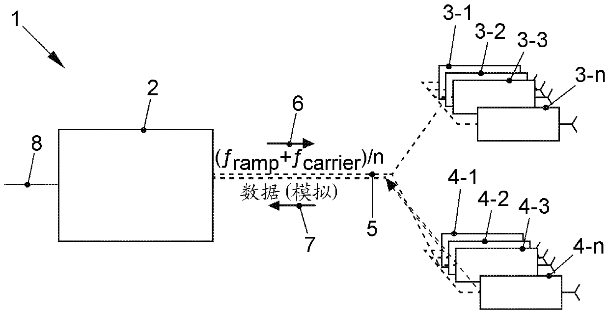
[0032] exist figure 1 A schematic diagram of an embodiment of a radar system 1 is shown in . For the sake of illustration, the optical connections are shown in this case by means of dashed lines. The radar system 1 includes a central unit 2, radar transmitting units 3-1, 3-2, 3-3, ..., 3-n, radar receiving units 4-1, 4-2, 4-3, ..., 4- n and glass fiber5.

[0033] Central unit 2 communicates with radar transmitting units 3-1, 3-2, 3-3, ..., 3-n and radar receiving units 4-1, 4-2, 4-3, ..., 4-n via glass fiber 5 connect. It should be noted in this case that, depending on the configuration of the radar system 1 , the connection by means of the glass fibers 5 is used jointly at least in sections. Of course, each radar transmitting unit 3-1, 3-2, 3-3, ..., 3-n and radar receiving unit 4-1, 4-2, 4-3, ..., 4-n can then pass through non-common Each waveguide is connected to the glass fiber 5 respectively.

[0034] The optical radar drive signal 6 is generated in the central unit...


PUM


Abstract

The invention relates to a radar system. The radar system having at least one radar transmission unit, at least one radar reception unit, a central unit, and a glass fiber for connecting these units,wherein the central unit has a central optical transmission unit to provide an optical radar driver signal, and wherein the at least one radar transmission unit has an optical reception unit and a radar transmitter, wherein the optical reception unit receives the optical radar driver signal and converts the optical radar driver signal into an electrical radar driver signal and provides the electrical radar driver signal for driving the radar transmitter, wherein the at least one radar reception unit includes a radar receiver, a mixer and an optical modulation unit. the mixer is configured to mix the radar echo signals received by the radar receiver and the electric radar driver signals; the optical modulation unit is configured to convert the mixed signals into optical radar driver signalsand couple the optical radar driver signals to at least one glass fiber; and the central unit evaluates the modulated signals. Also disclosed is an associated method.

Description

technical field [0001] The invention relates to a radar system and a method for operating a radar system. Furthermore, the invention relates to a central unit, a radar transmitter unit and a radar receiver unit of such a radar system. Background technique [0002] Within the scope of passive safety systems (passive Sicherheitssysteme) in motor vehicles, as well as for autonomous driving in levels 4 and 5, there is a special need for the distinction of road users not only for the protection of passengers but also for the protection of other road users. meaningful. For this, safe environmental monitoring (Umfelderfassung) is required. In order to guarantee this, the surroundings of the motor vehicle must be detected with the highest possible resolution in all three spatial dimensions. Modern camera systems and LIDAR systems are able to ensure this environment detection, but their quality is compromised or they fail completely in poor visibility situations, for example in fo...

Claims


Application Information

Patent Timeline
IPC IPC(8): G01S7/02G01S7/35G01S13/34G01S13/87G01S13/931G01S17/89
CPCG01S7/03G01S7/35G01S13/34G01S13/878G01S13/931H04B10/2575H04B2210/006G01S17/89G01S7/003G01S7/032
Inventor T.施奈德J.舍贝尔F.施瓦陶S.普罗伊斯勒H.李C.舍伊特M.施文克特T.巴格多纳特H.库尔茨
Owner VOLKSWAGEN AG
Why Eureka
Try Eureka