
Stator structure based on disc type permanent-magnetism motor winding

A permanent magnet motor and stator structure technology, applied in the shape/style/structure of winding conductors, etc., can solve the problems of difficulty in increasing power density, reducing stator utilization rate, occupying a large space, etc., to achieve output performance improvement, space The effect of full utilization and full utilization of space

Pending Publication Date: 2019-06-04
上海崴崖实业有限公司
View PDF0 Cites 4 Cited by
  • Summary
  • Abstract
  • Description
  • Claims
  • Application Information

AI Technical Summary

Problems solved by technology

Therefore, under the same current density, the outer end is generally 6 times larger than the effective conductor, and the inner end is 3 degrees larger than the effective conductor width. The inner and outer ends will occupy a large space, which will reduce the utilization rate of the stator and affect the output.
For the inner diameter of the already narrow space, it will appear very "crowded", making wiring more difficult, affecting heat dissipation, and limiting the increase in current, especially when the number of slots per pole and phase is large, this effect will be more significant
The more slots per pole and phase, the more ends, the larger the space occupied, the greater the copper loss, and the lower the efficiency, making it difficult to increase the power density

Method used


Image

  • Stator structure based on disc type permanent-magnetism motor winding
  • Stator structure based on disc type permanent-magnetism motor winding
  • Stator structure based on disc type permanent-magnetism motor winding

Examples


Embodiment Construction

[0031] In order to more clearly illustrate the embodiments of the present invention or the technical solutions in the prior art, the specific implementation manners of the present invention will be described below with reference to the accompanying drawings. Obviously, the accompanying drawings in the following description are only some embodiments of the present invention, and those skilled in the art can obtain other accompanying drawings based on these drawings and obtain other implementations.

[0032] In order to make the drawing concise, the parts related to the present invention are only schematically shown in each drawing, and they do not represent the actual structure of the product.

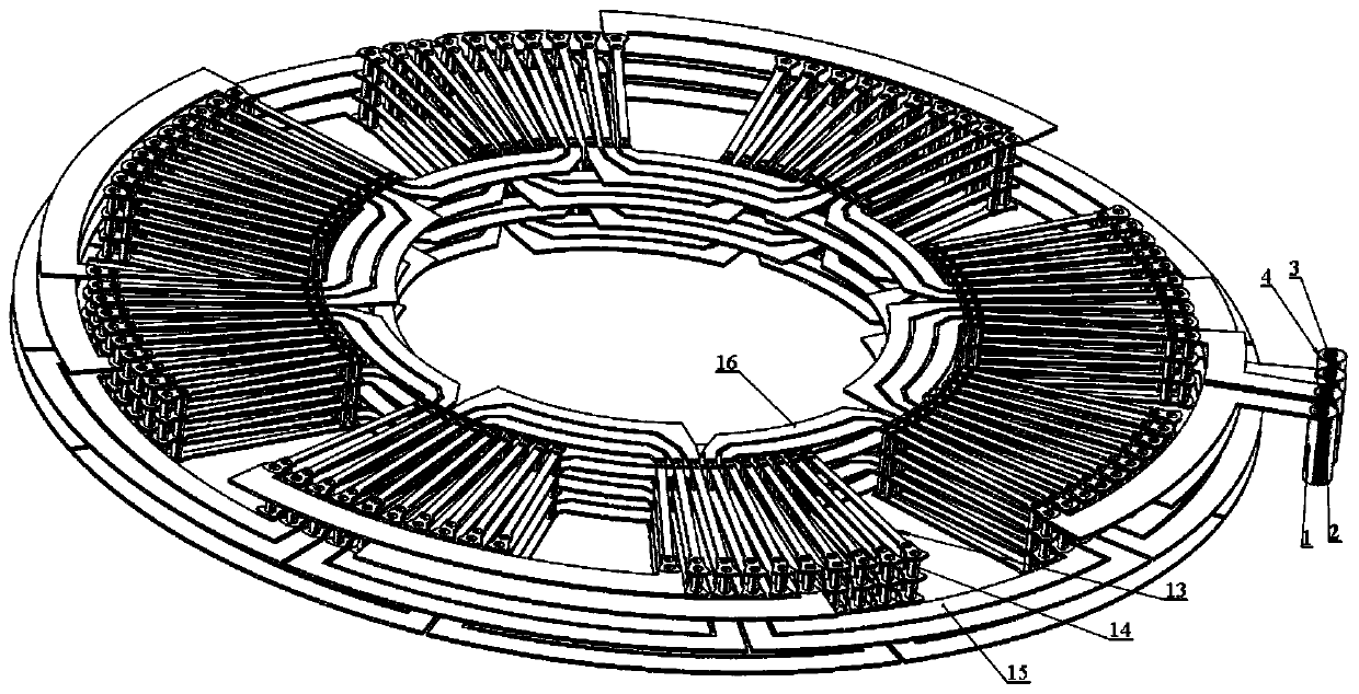
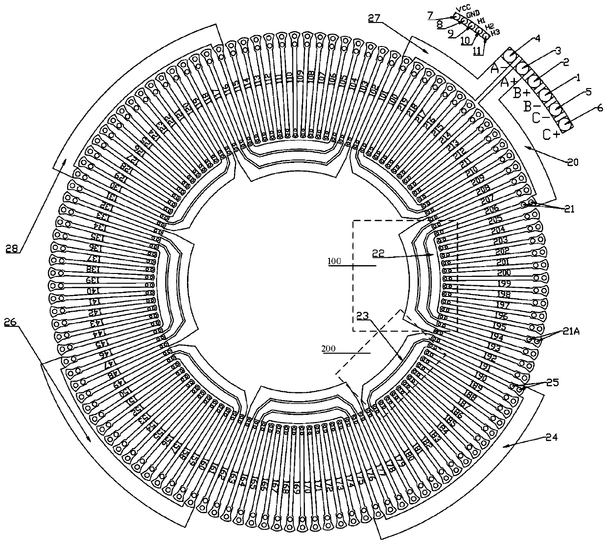
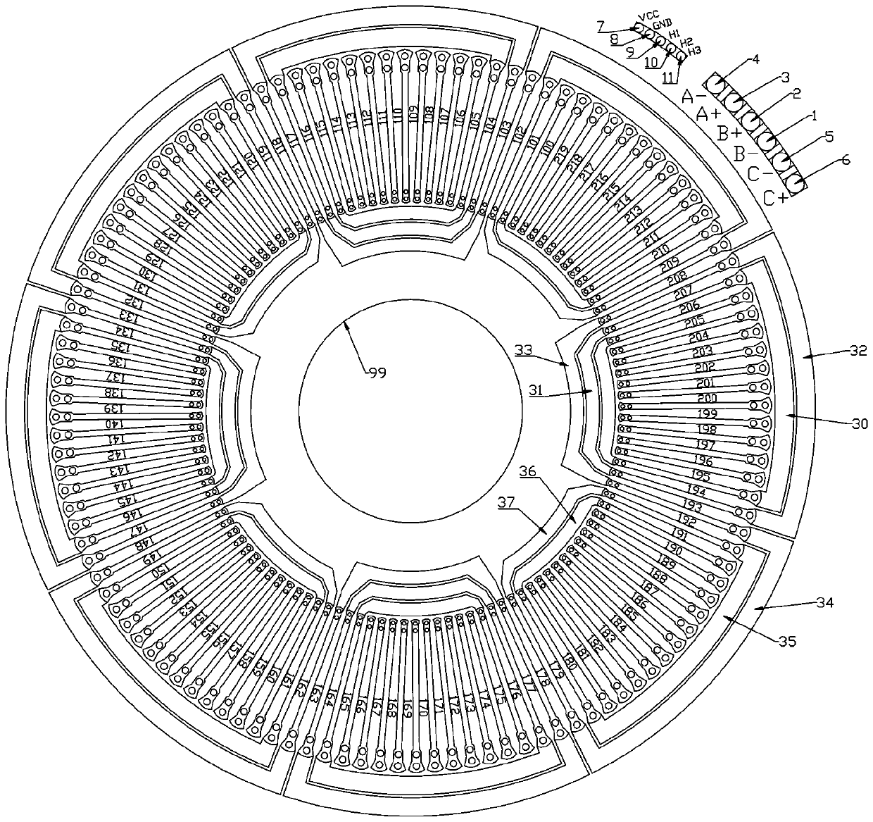
[0033] The present invention provides a stator structure based on disc permanent magnet motor windings, refer to figure 1 shown; including: at least 6 layers or 6N layers of PCB boards, and Hall sensors; each layer of the PCB board is provided with: multiple sets of outer ends, winding...


PUM


Abstract

The invention discloses a stator structure based on a disc type permanent-magnetism motor winding. The stator structure comprises a PCB with at least 6 or 6N layers, and a Hall sensor; each PCB layeris provided with outer end portions, a winding setting part and inner end portions; each PCB layer is provided with at least three windings, and each winding is provided with two wiring ends correspondingly; the wiring ends are arranged in the outer end portions; each winding coil is printed and arranged in the corresponding outer end portion; the winding coil is uniformly printed on the winding set part along the circumferential direction, and the length of the winding coil is arranged and printed in parallel along the radial direction without overlapping; the same phase of winding coils on the PCB layers are connected via the outer and inner end portions; the Hall sensor is arranged in the outer end portions with an angle; and the layers in the PCB are connected via through holes.

Description

technical field [0001] The invention relates to the field of motors, in particular to a stator structure based on a disc permanent magnet motor winding. Background technique [0002] The disc motor is different from the traditional radial motor. The stator and rotor of the disc motor are arranged along the axial direction. There are single rotor single stator, intermediate stator, multi-disk and other structures. Traditional radial motors have some difficulties that are not easy to solve, such as torque ripple, poor heat dissipation, low utilization of rotor core, etc. Therefore, disc motors began to receive more and more attention in the 1940s. At present, disc motors are widely used in flywheel energy storage systems, mechatronic equipment and other fields. PCB stator disc permanent magnet motor is a combination of printed circuit board technology and disc motor technology. The stator adopts PCB technology and has no stator core, so the motor is simple to manufacture, sm...

Claims


Application Information

Patent Timeline
Patent Type & Authority Applications(China)
IPC IPC(8): H02K3/26H02K3/28H02K3/24
Inventor 林晨王晓远
Owner 上海崴崖实业有限公司
Learn More