Connection mechanism with three rotational degrees of freedom, robot, robot arm, and robot hand

A technology of connection mechanism and degrees of freedom, applied in the directions of manipulators, program-controlled manipulators, joints, etc., can solve problems such as joint enlargement, and achieve the effect of simple structure

Inactive Publication Date: 2019-06-04
MITSUBISHI ELECTRIC CORP
View PDF3 Cites 2 Cited by
  • Summary
  • Abstract
  • Description
  • Claims
  • Application Information

AI Technical Summary

Problems solved by technology

In such a humanoid robot, it is necessary to arrange gears at the joints acco

Method used


Image

  • Connection mechanism with three rotational degrees of freedom, robot, robot arm, and robot hand
  • Connection mechanism with three rotational degrees of freedom, robot, robot arm, and robot hand
  • Connection mechanism with three rotational degrees of freedom, robot, robot arm, and robot hand

Examples


Example Embodiment

[0135] Embodiment 1.

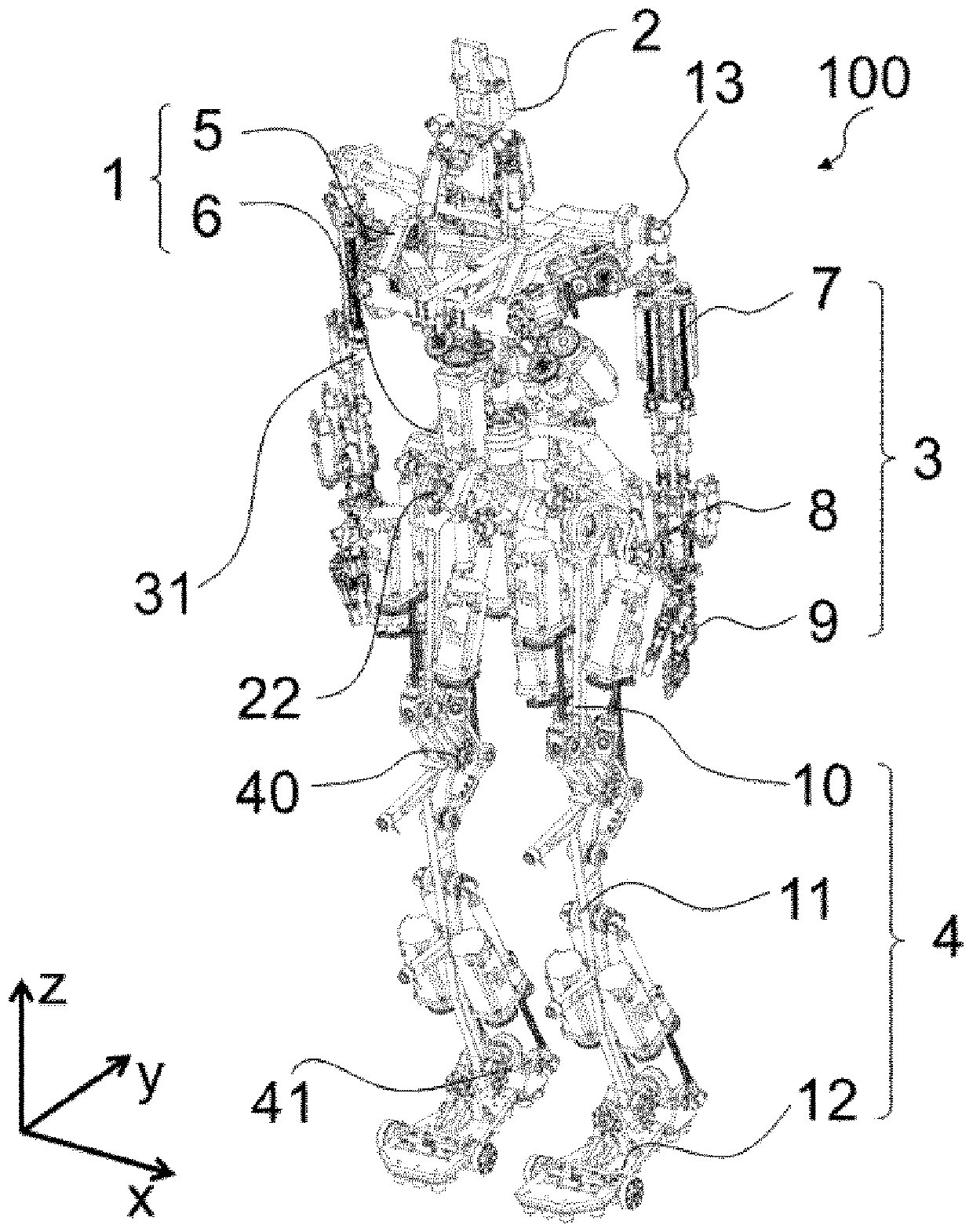
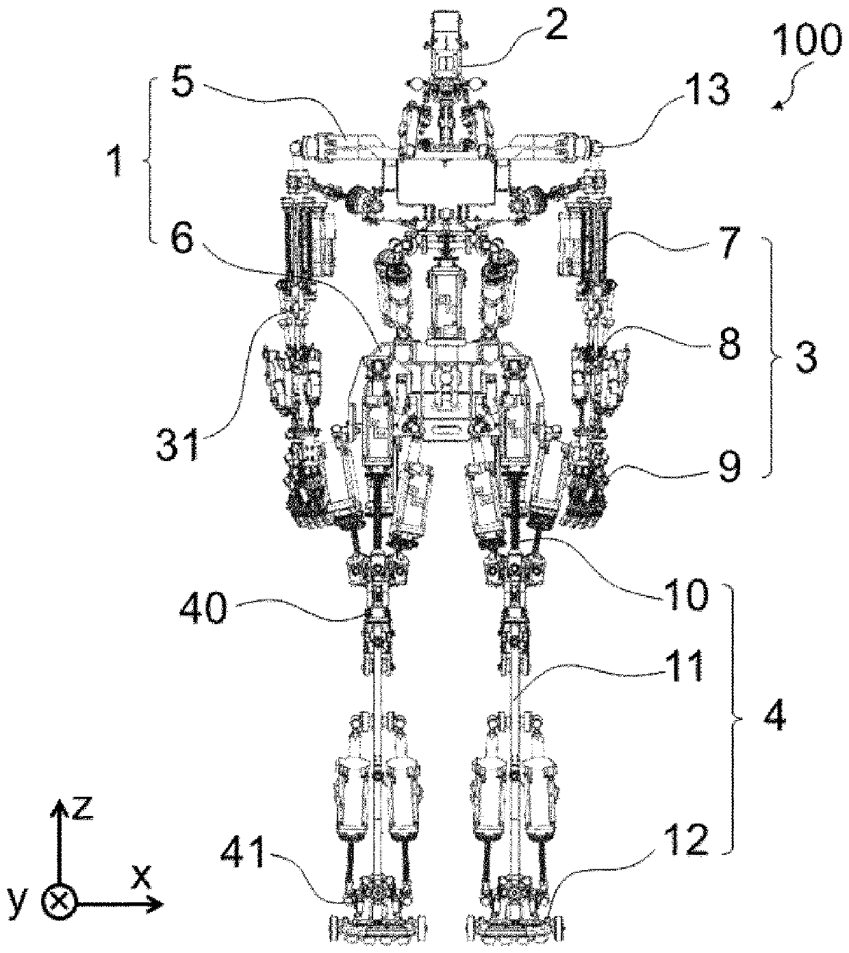
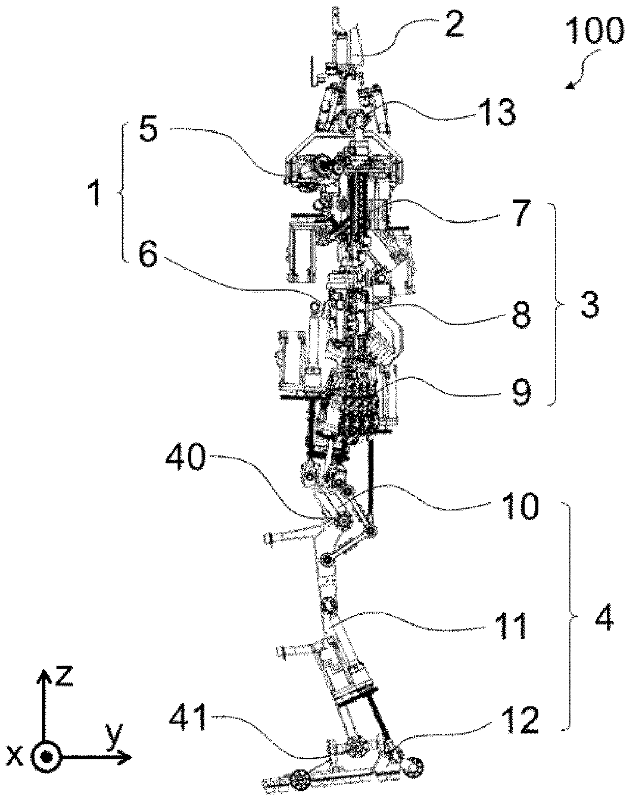
[0136] figure 1 It is a perspective view of the humanoid robot 100 according to Embodiment 1 of the present invention. in figure 2 , image 3 , Figure 4 with Figure 5 A front view, a left view, a rear view, and a plan view of the humanoid robot 100 are shown in respectively. in Image 6 A perspective view explaining the skeletal structure of the humanoid robot 100 is shown in FIG. in Figure 7 , Figure 8 , Picture 9 with Picture 10 A front view, a left view, a rear view, and a plan view in the case where the humanoid robot 100 is represented only by bones are shown in FIG. Let the axis in the left-right direction of the humanoid robot 100 be the X axis, the axis in the front-rear direction be the Y axis, and the axis in the height direction be the Z axis. Set the direction from right to left as the positive direction of the X axis, the direction from front to back as the positive direction of the Y axis, and the direction from top to bottom as the p...

Example Embodiment

[0745] Implementation mode 2.

[0746] The second embodiment is a case where the knee drive link 42 that drives the knee joint 40 is connected only to the lower leg 11 side. Figure 86 It is a perspective view of a humanoid robot 100X according to Embodiment 2 of the present invention. The front view, left view, rear view and plan view of the humanoid robot 100X are shown in Figure 87 , Figure 88 with Figure 89 in.

[0747] In the humanoid robot 100X, one end of the knee drive link 42L is not attached to the thigh 10X. One end of the knee drive link 42L is only attached to the lower leg 11X. In the humanoid robot 100X, when the knee joint section 40X is largely bent until the thigh section 10X and the lower leg section 11X are substantially parallel, the force for extending the knee joint section 40X may not be sufficiently output. When there is no need to adopt a posture such that the knee joint portion 40X is largely bent, the humanoid robot 100X can be used in the same mann...

Example Embodiment

[0748] Implementation mode 3.

[0749] The third embodiment is a case where an actuator that changes the angle formed between the toe portion and the foot body portion is provided. in Figure 90 , Figure 91 , Figure 92 with Figure 93 A plan view, a left view, a front view, and a perspective view of the left leg of the humanoid robot 100Y according to the third embodiment of the present invention are shown.

[0750] The foot 12Y of the humanoid robot 100Y has a toe driving actuator 47 that changes the angle formed by the foot main body 12A and the toe 12B. The toe part driving actuator 47 is arranged longitudinally with the ankle joint part 41 and arranged on the toe part 12B side. The foot body part 12A is provided with a foot body part side link attachment part J43. The foot main body side link attachment portion J43 is rotatably attached to one end of the toe portion driving link 47L. The toe portion 12B is provided with a toe-side link attachment portion J44, and the toe-s...


PUM


Abstract

The purpose of the present invention is to enable a connection mechanism with three rotational degrees of freedom, which is required for a robot capable of performing human-like movements, to be constructed by using a simple structure without restrictions being imposed on movements within a movable range. The connection mechanism is provided with: a joint part 18 for rotatably connecting a secondmember 5 to a first member 6 with three rotational degrees of freedom, including rotation about a torsion axis 56; three actuators 19, 20, 21 each having a variable-length link 19L, 20L, 21L, the length of which can be changed, and a drive source 19M, 20M, 21M for generating a force for changing the length of the variable-length link 19L, 20L, 21L; and three first member-side link attachment partsJ10, J8, J9 and three second member-side link attachment parts J5, J6, J7 disposed on the first member 6 and on the second member 5, respectively, such that a variable-length link 19L, 20L, 21L twisted with respect to the torsion axis 56 is present in each state within a movable range of the joint part 18.

Description

technical field [0001] The present invention relates to a connection mechanism with three rotation degrees of freedom, a robot using the connection mechanism with three rotation degrees of freedom, a robot arm and a robot hand, wherein the above connection mechanism with three rotation degrees of freedom is included in a robot that can realize actions close to human used in joints. Background technique [0002] A humanoid robot that has a body, arms, feet, and a head similar to humans is being developed. Conventional humanoid robots are generally of the type in which motors and gears are arranged on joints, and joint intersections are arranged on their axes. In such a humanoid robot, it is necessary to arrange gears at the joints according to the degree of freedom of rotation, and the joints become large. A bipedal walking robot is proposed, in which bones are connected by joints, and for each joint, the joints are driven with two rotational degrees of freedom by using the...

Claims


Application Information

Patent Timeline
IPC IPC(8): B25J17/00B25J5/00F16H21/46
CPCB62D57/032B25J9/0057B25J9/102B25J17/0283B25J17/0258B25J15/0009B25J15/0213B25J9/106B25J15/10B25J9/144F16H25/20F15B2211/7107F15B15/14F15B11/10F16H19/001F16H2025/2043F15B2211/7053F15B15/06F16H21/46B25J17/00B25J5/00
Inventor 川口升山内秀孝服部友哉广濑光史
Owner MITSUBISHI ELECTRIC CORP
Why Eureka
Try Eureka