
Filtering device for recycling water-based cleaning solution used for optical glass lenses

A technology of optical glass and filter device, which is applied in the direction of filtration separation, filter circuit, fixed filter element filter, etc. It can solve the problems that the mesh of the filter screen is easily blocked and affects the filtration efficiency, so as to improve the filtration efficiency and avoid blockage Effect

Pending Publication Date: 2019-06-07
丹阳广丰光学器材有限公司
View PDF12 Cites 9 Cited by
  • Summary
  • Abstract
  • Description
  • Claims
  • Application Information

AI Technical Summary

Problems solved by technology

[0004] Optical glass lenses need to use water-based cleaning solution in the production process, and the used water-based cleaning solution is generally recycled through the filter device to avoid waste, but the filter screen of the existing water-based cleaning solution filter device Pores are easily clogged which affects filtration efficiency

Method used


Image

  • Filtering device for recycling water-based cleaning solution used for optical glass lenses
  • Filtering device for recycling water-based cleaning solution used for optical glass lenses

Examples


Embodiment 1

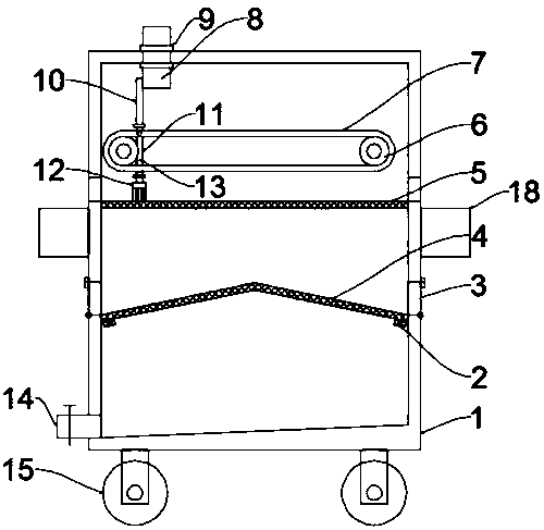
[0022] see figure 1 , in an embodiment of the present invention, a water-based cleaning liquid recovery and utilization filter device for optical glass lenses, including a box body 1, a first filter screen 5 and a second filter screen 4, and the four corners of the bottom of the box body 1 are installed There are supporting legs, and rollers 15 are installed at the bottom of the supporting legs. The rollers 15 are self-locking rollers to facilitate the movement of the device. One side of the bottom of the box body 1 is connected with a liquid outlet pipe 14, and the bottom of the inner cavity of the box body 1 is directed towards the liquid outlet. One side of the pipe 14 is inclined to facilitate liquid drainage. The first filter screen 5 and the second filter screen 4 are installed at intervals from top to bottom in the box body 1, and the liquid inlet pipe 8 is connected to the top of the box body 1. A drive mechanism for driving the liquid inlet pipe 8 to move left and rig...

Embodiment 2

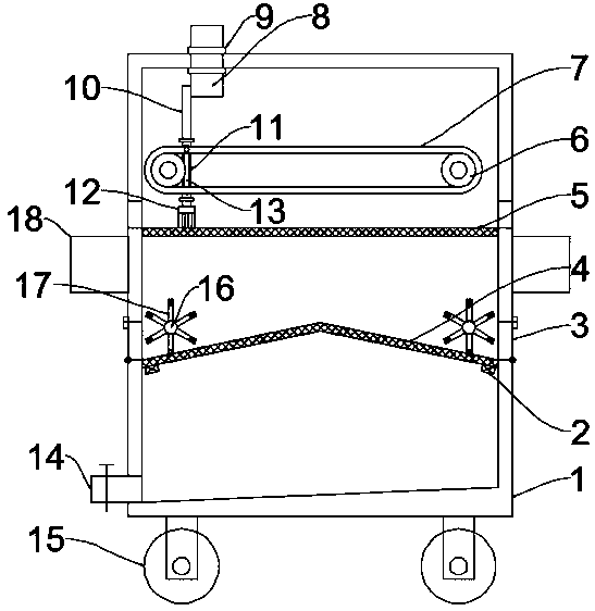
[0024] see figure 2 The difference between this embodiment of the present invention and Embodiment 1 is that a cleaning mechanism is installed above both sides of the second filter screen 4 in the box body 1, and the cleaning mechanism includes an installation shaft 16 and a brush plate 17. One end of the mounting shaft 16 is fixedly connected with the output shaft of the motor through a coupling, and a plurality of brush plates 17 are fixed circumferentially and equidistantly on the mounting shaft 16, and the brushes at the ends of the brush plates 17 are in contact with the top of the second filter screen 4, When it is necessary to discharge sundries, start the motor, and the motor drives the brush plate 17 to rotate to the side close to the miscellaneous discharge door 3 through the installation shaft 16, thereby continuously pushing the sundries on the second filter screen 4 to the miscellaneous discharge door 3 to speed up Trash removal speed.

[0025] The working princ...


PUM


Abstract

The invention discloses a filtering device for recycling water-based cleaning solution used for optical glass lenses, relates to the technical field of filtering devices, and mainly aims to solve theproblem that the filtering efficiency is influenced due to the fact that meshes of a filter screen of an existing water-based cleaning fluid filtering device are liable to be blocked. The filtering device comprises a box body, a first filter screen and a second filter screen. A driving mechanism for driving the liquid inlet pipe to move left and right is arranged above the first filter screen. Thedriving mechanism comprises two groups of belt transmission mechanisms, a movable plate and a connecting rod. The filtering device is provided with a driving mechanism, wherein brush strips are installed at the bottom of a movable plate, two sets of belt transmission mechanisms drive the movable plate to move left and right, and the movable plate drives a liquid inlet pipe to move left and rightthrough a connecting rod, so that cleaning liquid is dispersed, and the cleaning liquid is prevented from falling to one position of a first filter screen to cause blockage of first filter screen holes; meanwhile, the brush strips move left and right to brush impurities on the first filter screen towards the two ends of the first filter screen, so that meshes of the first filter screen are prevented from being blocked, and the filtering efficiency is further improved.

Description

technical field [0001] The invention relates to the technical field of filtering devices, in particular to a filtering device for recycling and utilizing water-based cleaning fluid for optical glass lenses. Background technique [0002] Optical glass is mixed with oxides of high-purity silicon, boron, sodium, potassium, zinc, lead, magnesium, calcium, barium, etc. according to a specific formula, melted at high temperature in a platinum crucible, stirred evenly with ultrasonic waves, and removed air bubbles; The temperature is lowered slowly over time to avoid internal stress in the glass block. The cooled glass blocks must be measured by optical instruments to check whether the purity, transparency, uniformity, refractive index and dispersion rate meet the specifications. Qualified glass blocks are heated and forged to form optical lens blanks. [0003] Water-based cleaning agents use the wetting, emulsifying, penetrating, dispersing, and solubilizing effects of surfactan...

Claims


Application Information

Patent Timeline
Patent Type & Authority Applications(China)
IPC IPC(8): B01D36/04B01D29/64
Inventor 曹小兵
Owner 丹阳广丰光学器材有限公司
Learn More