Al technical title is built by PatSnap Al team. It summarizes the technical point description of the patent document.
A technology of dust removal equipment and optical lenses, which is applied in the field of optical lenses, can solve the problems of not being able to clean lenses of different sizes, and the size of the lens support groove cannot be adjusted, so as to increase the efficiency of dust removal, avoid manual turning, and strengthen the cleaning effect. Effect
Pending Publication Date: 2019-06-07
江苏欧达光学有限公司
View PDF1 Cites 2 Cited by
Summary
Abstract
Description
Claims
Application Information
AI Technical Summary
This helps you quickly interpret patents by identifying the three key elements:
Problems solved by technology
Method used
Benefits of technology
Problems solved by technology
[0004] A lens dust removal device in the above-mentioned patent has the following disadvantages: after the lens is placed on the equipment, it can only clean the dust on one side of the lens, and when cleaning the other side, the lens needs to be turned over manually. Suitable for cleaning lenses of different sizes
Method used
Image
Click on the blue label to locate the original text in one second.
Reading with bidirectional positioning of images and text.
Examples
Embodiment Construction
[0021] The following will clearly and completely describe the technical solutions in the embodiments of the present invention with reference to the accompanying drawings in the embodiments of the present invention. Obviously, the described embodiments are only some, not all, embodiments of the present invention.
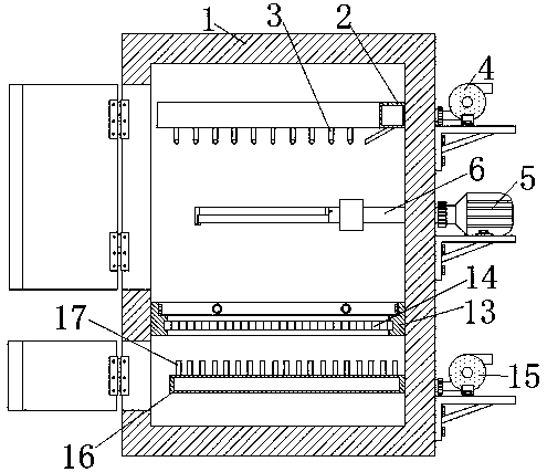
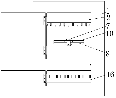
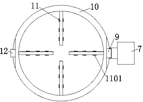
[0022] refer to Figure 1-3 , a kind of optical lens surface dust removal equipment, including a box body 1, the inner wall of the box body 1 near the top is fixed with a blowing part by bolts, the blowing part includes an annular air outlet pipe 2 fixed on the inner wall around the box body 1 by bolts, and the outlet The outer wall of the bottom of the air duct 2 is provided with equidistantly distributed first installation holes, and the inner wall of the first installation hole is welded with nozzles 3 arranged obliquely. 4. The first air pump 4 is fixed on the outer wall of one side of the box body 1 through a bracket, and a round hole is opened in the center of ...
PUM
Abstract
The invention discloses surface dust removing equipment for an optics lens. The surface dust removing equipment for the optics lens comprises a box body, a blowing part is fixed to the portion, closeto the top, of the inner wall of the box body, and a first air pump is connected to a blowing device and fixed to the outer wall of one side of the box body through a bracket; and a circular hole is formed in the center of the inner wall of one side of the box body, a bearing is sleeved with the inner wall of the circular hole, a bearing part is sleeved with the bearing and comprises a transmission rod sleeved with the inner wall of the bearing, the end, located in the box body, of the transmission rod is sleeved with a connecting part, a circular-ring-shaped bottom bracket is welded to the bottom of the end, far away from the transmission rod, of the connecting rod, a hinge block is hinged to the top of the end, far away from the transmission rod, of the connecting part, and a circular-ring-shaped top bracket is welded to the end, far away from the transmission rod, of the hinge block. According to the surface dust removing equipment for the optics lens, the purpose of removing dust on the two faces of the lens at a time is achieved, manual face turning is avoided, the dust removing working efficiency is improved, the surface dust removing equipment can adapt to the lens with moredifferent sizes, and the practicability is high.
Description
technical field [0001] The invention relates to the technical field of optical lenses, in particular to an optical lens surface dust removal device. Background technique [0002] Lens is a transparent material with one or more curved surfaces made of optical materials such as glass or resin. After polishing, it is often used on various optical devices to change the reflection or refraction path of light to achieve people's ideal imaging effect. [0003] After searching, the Chinese patent authorization number is CN207188375U, which discloses a lens dust removal device including: a base, a tray slidably arranged on the base, and a dust suction pipe arranged under the base, and a set is set on the tray. There is a card slot for placing lenses, and a dust suction port connected with the dust suction pipe is opened on the base, and the dust suction pipe is connected to a dust suction pump. [0004] A lens dust removal device in the above-mentioned patent has the following disad...
Claims
Application Information
Patent Timeline
Application Date:The date an application was filed.
Publication Date:The date a patent or application was officially published.
First Publication Date:The earliest publication date of a patent with the same application number.
Issue Date:Publication date of the patent grant document.
PCT Entry Date:The Entry date of PCT National Phase.
Estimated Expiry Date:The statutory expiry date of a patent right according to the Patent Law, and it is the longest term of protection that the patent right can achieve without the termination of the patent right due to other reasons(Term extension factor has been taken into account ).
Invalid Date:Actual expiry date is based on effective date or publication date of legal transaction data of invalid patent.