Oil press applied to forging

A technology for hydraulic presses and forgings, applied in the field of hydraulic presses, can solve the problems of unfavorable long-term use of hydraulic presses, inconvenient wiping and smearing, and unfavorable use by workers, and achieves the effects of automatic maintenance, improved heat dissipation, and simple structure.

Inactive Publication Date: 2019-06-07
郴州市信诚机械有限公司
View PDF0 Cites 4 Cited by
  • Summary
  • Abstract
  • Description
  • Claims
  • Application Information

AI Technical Summary

Problems solved by technology

[0003] The existing hydraulic press technology for forging is relatively mature. During the daily maintenance of the hydraulic press, it is necessary to wipe off the dust and impurities on the hydraulic column of the hydraulic press, and then apply lubricating oil evenly on the hydraulic column. This maintenance process requires workers to climb up It is inconvenient to wipe and smear manually, which brings a large workload to the work, and there are certain safety hazards, which is not conducive to the use of workers. When the hydraulic machine works with the oil pipes through the oil pump, it will generate more heat. Air-cooled heat dissipation, the heat dissipation effect is average, which is not conducive to the long-term use of the hydraulic press

Method used


Image

  • Oil press applied to forging
  • Oil press applied to forging
  • Oil press applied to forging

Examples


Embodiment Construction

[0023] The following will clearly and completely describe the technical solutions in the embodiments of the present invention with reference to the accompanying drawings in the embodiments of the present invention. Obviously, the described embodiments are only some, not all, embodiments of the present invention. Based on the embodiments of the present invention, all other embodiments obtained by persons of ordinary skill in the art without making creative efforts belong to the protection scope of the present invention.

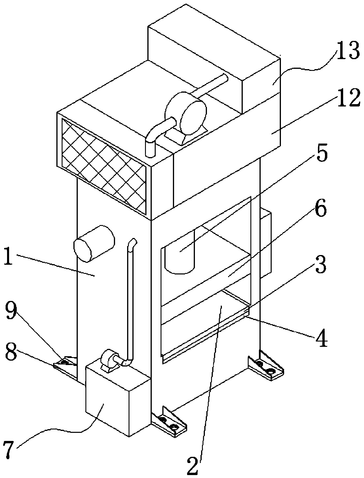
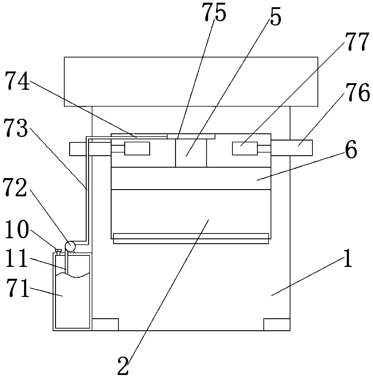
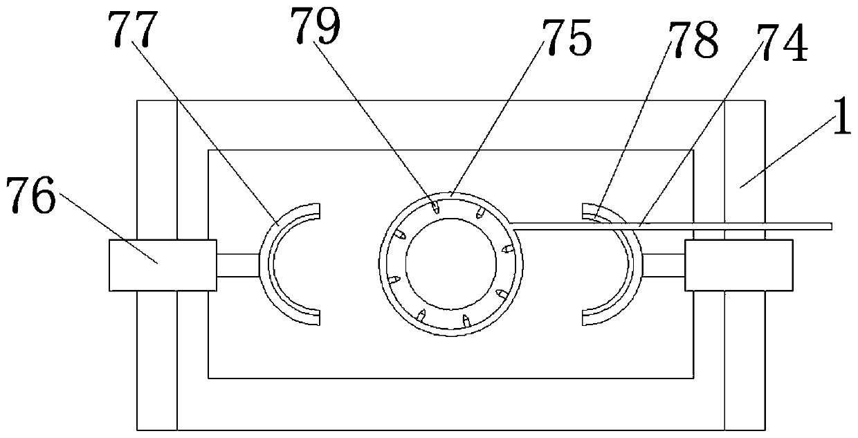
[0024] see Figure 1-5, the present invention provides a technical solution: a hydraulic press for forging, including a hydraulic press main body 1, a workbench 2, a lower template 3, a heat shield 4, a hydraulic column 5, an upper template 6, a hydraulic column wiping and lubricating assembly 7, and mounting feet 8. Install the screw hole 9, the liquid injection port 10, the oil suction pipe 11, the package box 12 and the water cooling and heat dissipation as...


PUM


Abstract

The invention discloses an oil press applied to forging. The oil press comprises an oil press main body, a worktable, a lower mold plate, a heat insulating plate, a hydraulic column, an upper mold plate and a hydraulic column wiping and lubricating component; the worktable is arranged on the inner wall of the middle part of the oil press main body; the lower mold plate is fixedly installed on theinner wall of the bottom end of the worktable; the heat insulating plate is arranged at the joint of the lower mold plate and the inner wall of the bottom end of the worktable; the upper mold plate isfixedly installed at the part, positioned above the lower mold plate, of the oil press main body by virtue of the hydraulic column; and the hydraulic column wiping and lubricating component is arranged on the outer wall of one side of the bottom end of the oil press main body. The oil press is relatively simple in structure and relatively high in automation level; by installation of the hydrauliccolumn wiping and lubricating component and cooperative use of a sponge cushion and a sprayer, the dust and impurities on the surface of the outer wall of the hydraulic column are wiped, the outer surface of the hydraulic column is totally coated with the lubricating oil, automatic maintenance of the hydraulic column of the oil press is realized, and the sponge cushion is connected by using glue,so the sponge cushion is beneficial to be replaced.

Description

technical field [0001] The invention relates to the technical field of hydraulic presses, in particular to a hydraulic press for forging. Background technique [0002] The hydraulic press (a type of hydraulic press) is a kind of special hydraulic oil as the working medium, the hydraulic pump as the power source, and the force of the pump to make the hydraulic oil enter the cylinder through the hydraulic pipeline, and then there are several groups of mutual cooperation in the cylinder. Seals, the seals in different positions are different, but they all play the role of sealing, so that the hydraulic oil cannot leak; finally, the hydraulic oil is circulated in the oil tank through the check valve to make the oil cylinder do work, so as to complete certain mechanical actions as the productivity. A kind of machinery; hydraulic presses are often used in the process of material forging, mainly used for stretch forming, rummaging, bending and stamping of metal sheet parts, and can ...

Claims


Application Information

Patent Timeline
Patent Type & Authority Applications(China)
IPC IPC(8): B21J9/12B21J13/00B30B15/00B30B15/34
Inventor 雷安灰雷诚
Owner 郴州市信诚机械有限公司
Why Eureka
Try Eureka