Drying equipment with limiting adjusting function

A technology of drying equipment and limit cylinder, which is applied in textiles and papermaking, removal of liquid/gas/steam, treatment of textile materials, etc. It can solve problems such as mutual entanglement and knotting, color deviation of textile fabrics, and large heat. To achieve the effect of ensuring uniformity and preventing winding and knotting

Active Publication Date: 2019-06-07
SUZHOU PULUN ELECTRONICS TECH CO LTD
View PDF11 Cites 2 Cited by
  • Summary
  • Abstract
  • Description
  • Claims
  • Application Information

AI Technical Summary

Problems solved by technology

[0004] The invention provides a limit adjustment drying equipment, which has the advantages of being convenient for the user to control the intensity and uniformity of the heating of the textile cloth and avoiding the intertwining and knotting of the dried cloth, which solves the problem of the existing drying equipment for printing and dyeing. The equipment generally uses a heating cylinder or a heat pipe to heat and dry the fabric after textile printing and dyeing. However, when the heating cylinder and heat pipe heat the textile fabric, the heat on the side close to the heat source is greater than that on the side far away from the heat source. Large, and it is not convenient for the user to control the uniformity of the heating of the textile fabric during the printing and dyeing process. Due to insufficient heating, the color tone of the textile fabric immediately after printing and dyeing may deviate; The slack in the woven fabric may easily cause the woven fabric to scatter, entangle with each other or even knotted

Method used


Image

  • Drying equipment with limiting adjusting function
  • Drying equipment with limiting adjusting function
  • Drying equipment with limiting adjusting function

Examples


Embodiment Construction

[0025] The following will clearly and completely describe the technical solutions in the embodiments of the present invention with reference to the accompanying drawings in the embodiments of the present invention. Obviously, the described embodiments are only some, not all, embodiments of the present invention. Based on the embodiments of the present invention, all other embodiments obtained by persons of ordinary skill in the art without making creative efforts belong to the protection scope of the present invention.

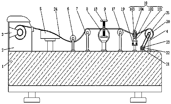
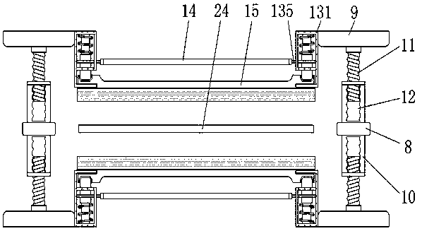
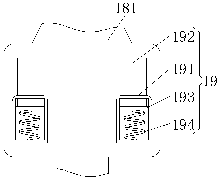
[0026] see Figure 1-4 , a limit adjustment drying equipment, including a body 1, a support frame 8 installed in the middle of the upper surface of the body 1 and an adjustment device 19 fixedly connected to the right side of the upper surface of the body 1, the upper surface of the body 1 is from left to right respectively The supporting platform 5, the rotary cylinder 6, the orientation cylinder I7 and the orientation cylinder II17 are fixedly installed, and...


PUM


Abstract

The invention relates to the technical field of drying equipment, and discloses drying equipment with a limiting adjusting function. The equipment comprises an equipment body, supporting frames are installed in the middle of the upper surface of the equipment body, an adjusting device is fixedly connected to the right side of the upper surface of the equipment body, a containing box is fixedly installed at the left side of the upper surface of the equipment body, and a textile fabric is movably sleeved with the containing box through a hanging rod. According to the drying equipment for textileprinting and dyeing, transverse plates, distance setting pillars, threaded rods and threaded holes cooperate with one another, the two distance setting pillars are internally provided with threaded holes with opposite threads, then a user conveniently rotates the two threaded holes simultaneously in situ, then cooling plates at the upper and lower sides of the threaded holes are moved simultaneously, thus the user conveniently controls the temperature of heat on the to-be-dried threaded holes through distance, and in this way, the user conveniently controls the heated intensity of the textilefabric; moreover, the fabric is heated through the straight cooling plates, and thus the heated uniformity of the fabric is guaranteed.

Description

technical field [0001] The invention relates to the technical field of drying equipment, in particular to a drying equipment for textile printing and dyeing. Background technique [0002] Printing and dyeing, also known as dyeing and finishing, is a processing method and a general term for pretreatment, dyeing, printing, finishing, washing, etc. The drying equipment for textile printing and dyeing is used for heating and drying during the production and processing of textiles. A drying equipment for the process. [0003] Existing drying equipment for printing and dyeing generally use heating cylinders or heat pipes to heat and dry the fabric after textile printing and dyeing. The heat on the side of the heat source is large, and it is not convenient for the user to control the uniformity of the heating of the textile fabric during the printing and dyeing process. Due to insufficient heating, the color tone of the textile fabric immediately after printing and dyeing may devi...

Claims


Application Information

Patent Timeline
IPC IPC(8): D06B15/00D06B23/02
Inventor 郑章鑫董李杰
Owner SUZHOU PULUN ELECTRONICS TECH CO LTD
Why Eureka
Try Eureka