
Undersea drilling rig mud circulation system and method

A circulatory system and mud technology, applied in earth-moving drilling, wellbore/well components, flushing wellbore, etc., can solve the problem of short service life of the subsea mud circulation system, avoid pipeline blockage failure, prolong service life, Deliver reliable effects

Active Publication Date: 2019-06-07
CHINA UNIV OF PETROLEUM (EAST CHINA)
View PDF19 Cites 2 Cited by
  • Summary
  • Abstract
  • Description
  • Claims
  • Application Information

AI Technical Summary

Problems solved by technology

[0004] Therefore, the technical problem to be solved by the embodiments of the present invention is that the service life of the submarine mud circulation system in the prior art is short

Method used


Image

  • Undersea drilling rig mud circulation system and method
  • Undersea drilling rig mud circulation system and method
  • Undersea drilling rig mud circulation system and method

Examples


Embodiment 1

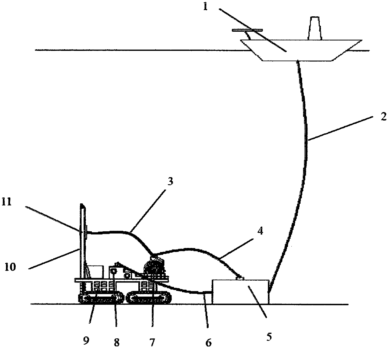
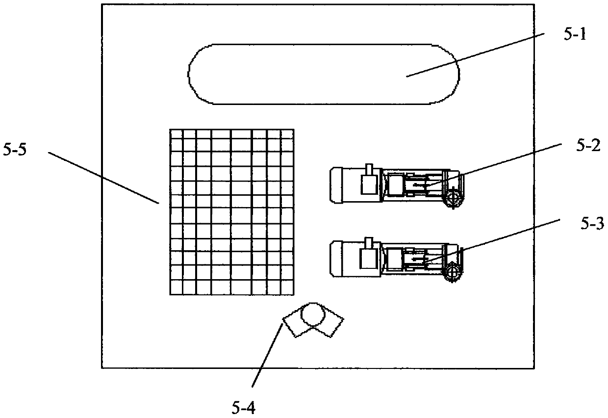
[0064] This embodiment provides a mud circulation system for a subsea drilling rig, which is especially suitable for deep-water drilling for oil or natural gas hydrate exploitation. Such as figure 1 As shown, the mud circulation system of the subsea drilling rig includes: auxiliary ship 1, umbilical cable 2, coiled tubing tension section 3, coiled tubing mud input pipeline 4, submarine mud processing device 5, wellhead mud recovery pipeline 6, coiled tubing 7, wellhead Device 8 , subsea drilling rig base 9 , injection head 11 and derrick 10 .

[0065] The auxiliary vessel 1 is located on the sea surface. One end of the umbilical cable 2 is connected with the auxiliary ship 1 , and the other end is connected with the seabed mud processing device 5 , which is used to provide a channel for injecting mud into the seabed and returning mud to the auxiliary ship 1 . Preferably, the umbilical cable contains at least three cavities, one is a power transmission cavity for placing tran...

Embodiment 2

[0074] This embodiment provides a mud circulation method for a subsea drilling rig, such as Figure 5 shown, including the following steps:

[0075] S1. Inject mud from the auxiliary vessel 1 into the coiled tubing 7;

[0076] S2. Return the mud from the wellhead device 8 to the seabed mud treatment device 5 through the wellhead mud recovery pipeline 6;

[0077] S3, the submarine mud processing device 5 performs the first filtering treatment on the mud;

[0078] S4. Return the mud processed by the seabed mud processing device 5 to the auxiliary ship 1 through the umbilical cable 2;

[0079] S5. The auxiliary ship 1 performs a second filtering process on the mud and stores it.

[0080] Preferably, the step of injecting mud from the auxiliary ship 1 into the coiled tubing 7 in S1 includes:

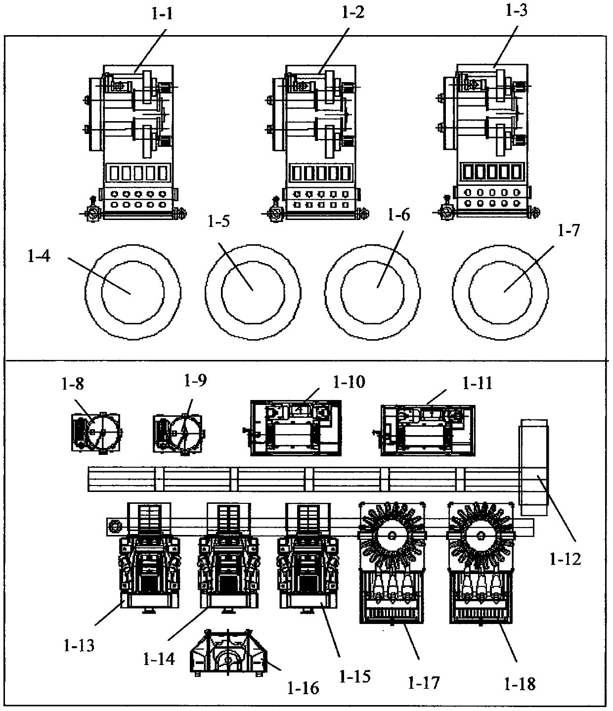
[0081] S11. Control the two mud pumps in mud pump one 1-1, mud pump two 1-2 and mud pump three 1-3 to pump the mud in the mud tank into the injection chamber of the umbilical cable 2, an...


PUM


Abstract

The invention discloses an undersea drilling rig mud circulation system and method, and relates to the technical field of deep-water drilling equipment. The undersea drilling rig mud circulation system comprises an auxiliary ship, an umbilical cord cable, a coiled tubing tensioning section, a coiled tubing mud input pipeline, an undersea mud treatment device, a wellhead mud recovery pipeline, coiled tubing, a wellhead device, an undersea drilling rig base, an injection head and a derrick; one end of the umbilical cord cable is connected with the auxiliary ship, and the other end of the umbilical cord cable is connected with the undersea mud treatment device for providing a channel for injecting mud into the seafloor and returning the mud to the auxiliary ship; and the undersea mud treatment device is used for outputting the mud injected from the umbilical cord cable to the coiled tubing mud input pipeline, filtering the mud returned from the wellhead mud recovery pipeline, and then outputting the mud to the auxiliary ship through the umbilical cord cable. The undersea drilling rig mud circulation system and method have the advantages that the conveying distance is long, and the service life is long.

Description

technical field [0001] The invention relates to the technical field of deepwater drilling equipment, in particular to a mud circulation system and method for a submarine drilling rig. Background technique [0002] At present, with the reduction of land and shallow sea oil and gas reserves and the increase of difficulty in exploitation, deep water areas have gradually become the hot spots of oil and gas exploration in the world. However, traditional land or offshore platform drilling rigs are difficult to meet the needs of deepwater drilling due to constraints such as water depth and formation. In addition, for traditional land or offshore platform drilling rigs, the distance between the mud system and the wellhead is close, and the transmission energy loss is small. However, the wellhead of the subsea drilling rig is located on the seabed, and it is hundreds of meters away from the mud system on the auxiliary ship. The transmission distance is long and the energy loss is lar...

Claims


Application Information

Patent Timeline
Patent Type & Authority Applications(China)
IPC IPC(8): E21B21/00E21B21/06
Inventor 崔俊国肖文生李康康永田梅连朋刘健赵海洋邹文强刘思缈刘广斗
Owner CHINA UNIV OF PETROLEUM (EAST CHINA)
Learn More