
Heavy oil recovery method integrating heat injection oil production and mechanical oil production

An extraction method and mechanical oil extraction technology, which are applied in the fields of fluid extraction, earth-moving drilling, wellbore/well components, etc., can solve the problems that the high temperature resistance performance of mechanical extraction tools cannot meet the requirements, the production effect is not ideal, and the extraction of heavy oil is restricted. Process and other problems, to achieve the effect of solving the contradiction between temperature resistance and heat injection and oil production and high temperature

Active Publication Date: 2019-06-07
天津克睿特维科技发展有限公司
View PDF5 Cites 1 Cited by
  • Summary
  • Abstract
  • Description
  • Claims
  • Application Information

AI Technical Summary

Problems solved by technology

[0005] 2. During operation, in order to meet the requirements of well control and environmental protection, the leakage of washing and killing fluids is inevitable. The lost washing and killing fluids have a cooling effect on the formation or heavy oil that has been heated and heated in the early stage, which will cause the oil to be removed after the operation. When harvesting by machine, the production effect is not ideal
[0006] In response to these shortcomings, people have been trying to realize the integration of the heat injection string and the mechanical mining string. The high temperature resistance cannot meet the requirements, so it has to be realized in two strings, which limits the process of heavy oil production and affects the production efficiency

Method used


Image

  • Heavy oil recovery method integrating heat injection oil production and mechanical oil production
  • Heavy oil recovery method integrating heat injection oil production and mechanical oil production

Examples


Embodiment Construction

[0040] Below in conjunction with accompanying drawing and embodiment the present invention will be further described:

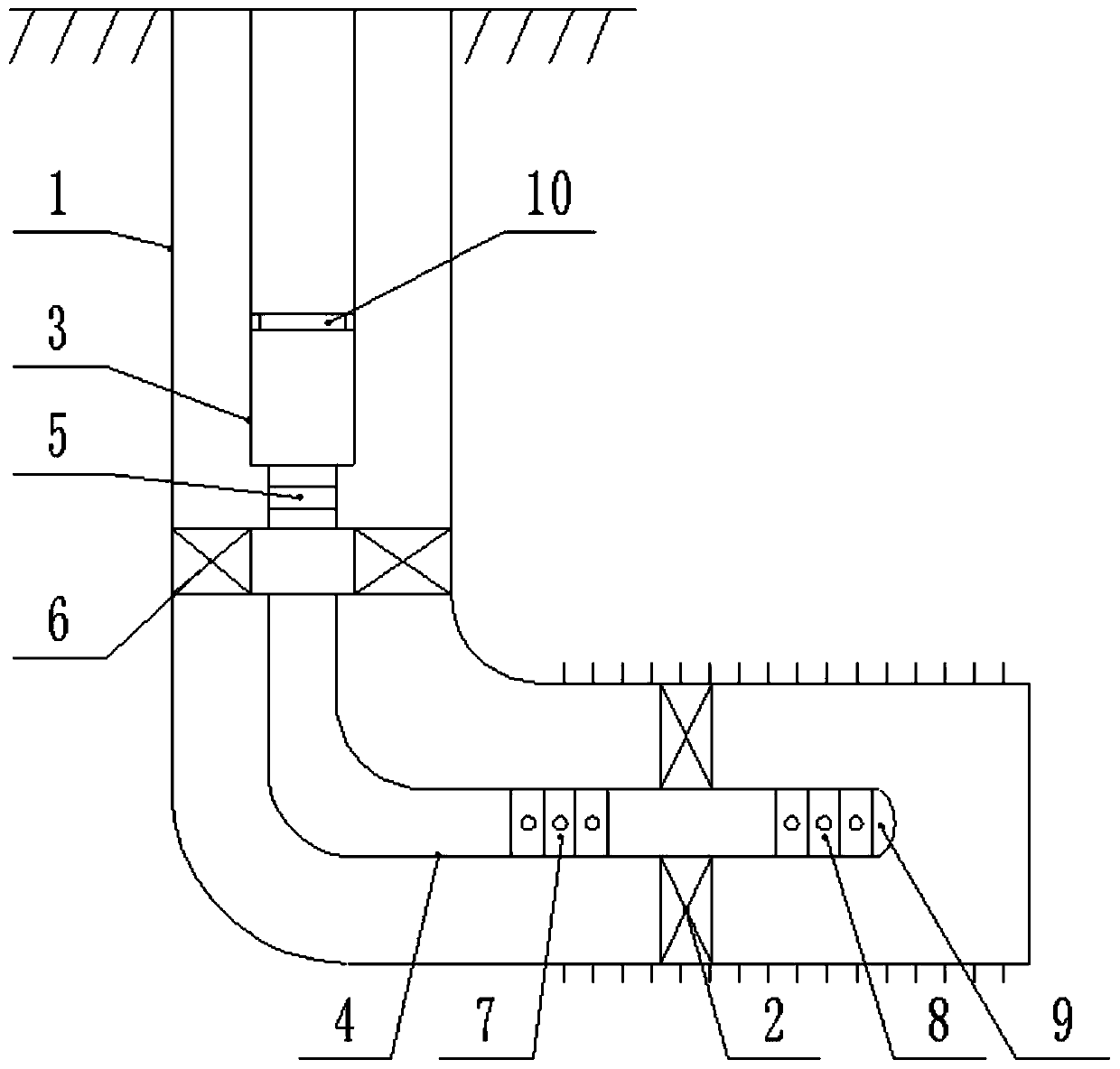
[0041] Such as Figure 1 to Figure 2 As shown, a heavy oil recovery method integrating thermal oil recovery and mechanical oil recovery, the specific steps are:

[0042] S1. Preparations

[0043] Design a high-temperature isolation packer 2 for deep setting in the wellbore 1;

[0044] S2, down into the heat injection column

[0045] Run the combined heat injection pipe string in the wellbore 1;

[0046] The heat injection string includes a casing / insulated oil pipe 3 and an oil pipe 4, a deep well safety valve 5 is provided between the casing / insulated oil pipe 3 and the oil pipe 4, and an insertion seal 6 is provided at the head end of the oil pipe 4 , the tail end of the oil pipe 4 passes through the high temperature isolation packer 2 in step S1, the oil pipe 4 is provided with an injection valve 7 at the front end of the high temperature isolation pac...


PUM


Abstract

The invention provides a heavy oil recovery method integrating heat injection oil production and mechanical oil production. The method includes the following concrete steps: S1. performing preparationwork; S2. placing a combined heat injection pipe column in a wellbore; S3. after placing the combined heat injection pipe column, installing an oil production tree, and implementing a heat injectionprocess after installing the oil production tree; S4. performing self-spraying production, measuring the temperature of produced fluid, and providing a basis for subsequent selection of a temperatureresistance level of a mechanical plucking machine tool; S5. placing the mechanical plucking machine tool; and S6. performing mechanical plucking. According to the method, the wellbore and a heat injection pipe column with large diameter are first placed, and then heat injection is performed; after the heat injection and the self-spraying production are completed, the heat injection pipe column isnot required to be moved, the oil production tree is not required to be removed, the mechanical plucking machine tool only needs to be connected by a continuous oil pipe, the mechanical plucking machine tool is sent to a predetermined position seat seal in the heat injection pipe column, then the mechanical plucking can be achieved, and so, the contradiction between temperature resistance of the mechanical plucking machine tool and high temperature of the heat injection oil production is solved well under existing technical conditions, and an important technical means is provided for development of heavy oil.

Description

technical field [0001] The invention relates to the field of heavy oil recovery, in particular to a heavy oil recovery method integrating thermal oil recovery and mechanical oil recovery. Background technique [0002] Due to the high viscosity of heavy oil, it is not suitable or will not flow naturally in the original state of the formation. At present, the most commonly used method for the exploitation of heavy oil fields is the thermal oil recovery process, that is to use the heat-sensitive effect of heavy oil to heat the underground heavy oil, so that the original heavy oil viscosity is greatly reduced, and then the economic development of heavy oil is realized. After the heavy oil is heated, its fluidity becomes better, and the energy of the corresponding fluid is increased by artificially injected hot steam or multi-element thermal fluid. The heavy oil can be produced by self-spraying at the initial stage, and the fluid energy gradually decreases with the self-spraying ...

Claims


Application Information

Patent Timeline
Patent Type & Authority Applications(China)
IPC IPC(8): E21B43/24
Inventor 高健明古明良杨文超
Owner 天津克睿特维科技发展有限公司
Learn More