Double-cylinder double-acting hydraulic reciprocating pump

A double-acting, reciprocating pump technology, applied in the direction of pumps, piston pumps, liquid displacement machinery, etc., can solve the problems of complex structure of inlet and outlet pipelines, increase of operation and maintenance costs, increase of operation failure points, etc., to achieve work The principle is simple and clear, the source of failure and the cost of operation and maintenance are reduced, and the control method is simple and reliable.

Pending Publication Date: 2019-06-07
HUNAN CREDO PUMP
View PDF11 Cites 4 Cited by
  • Summary
  • Abstract
  • Description
  • Claims
  • Application Information

AI Technical Summary

Problems solved by technology

[0004] However, in high-power occasions, the double-cylinder single-feed cannot meet the requirements of the working conditions, and both sides of the piston of the material cylinder need to be set as the working chamber. The existing patent is a double-cylinder double-feed method, which is equipped with 8 single Flow distribution to the control valve group, and a series of external pipelines to match the connection of the one-way control valve
Whether it is a double-cylinder single-feed plunger pump or a double-cylinder double-feed plunger pump, there are multiple feed pipes and discharge pipes on the pump barrel of the plunger pump, and the pipeline structure of the feed inlet and outlet is relatively complicated. The process is relatively complicated, which is extremely inconvenient for the early installation and later maintenance; at the same time, the double-cylinder double-feeding needs to be equipped with 8 one-way control valve groups, which has a complicated structure and high equipment cost. The point of failure in operation increases the cost of operation and maintenance

Method used


Image

  • Double-cylinder double-acting hydraulic reciprocating pump

Examples


Embodiment Construction

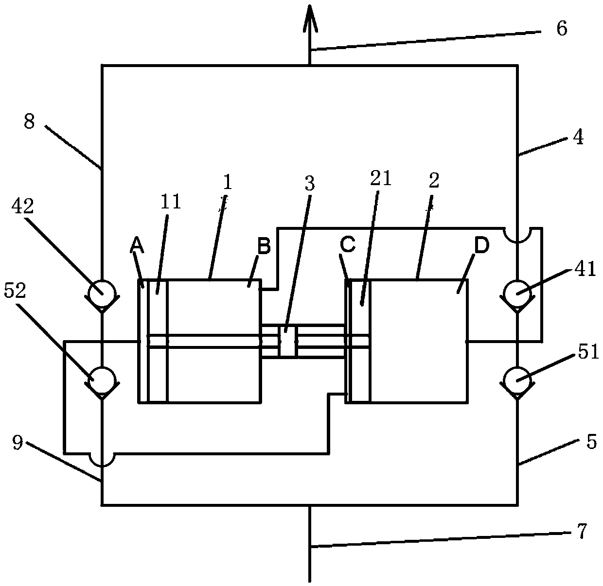
[0012] The present invention will be further described below in conjunction with the accompanying drawings.

[0013] Such as figure 1 As shown, the present invention includes two material cylinders 1, 2 and a hydraulic cylinder 3; the material cylinder 1 and the material cylinder 2 are respectively provided with a piston 11 and a piston 21; the hydraulic cylinder 3 is coaxial with the material cylinder 1 and the material cylinder 2, The hydraulic cylinder 3 is located between the material cylinder 1 and the material cylinder 2. The hydraulic cylinder 3 is a double-rod hydraulic cylinder. The two ends of the piston rod of the hydraulic cylinder 3 are respectively connected with the piston 11 and the piston 21, which can drive the piston 11 and the piston 21 in the same direction. move. The working chamber A of material cylinder 1 located on the left side of piston 11 communicates with the working chamber C of material cylinder 2 located on the left side of piston 21 through pi...


PUM


Abstract

The invention discloses a double-cylinder double-acting hydraulic reciprocating pump. The double-cylinder double-acting hydraulic reciprocating pump comprises two material cylinders and a hydraulic oil cylinder; pistons are arranged in the two material cylinders; the hydraulic oil cylinder is coaxial with the two material cylinders; a piston rod of the hydraulic oil cylinder is connected with thepistons in the two material cylinders; working cavities of the two material cylinders positioned on the left sides of the pistons communicate through pipes I; working cavities of the two material cylinders positioned on the right sides of the pistons communicate through pipes II; the pipes I are connected with a feed branch pipe I and a discharge branch pipe I; the pipes II are connected with a feed branch pipe II and a discharge branch pipe II; and one-way valves are arranged on the feed branch pipe I, the feed branch pipe II, the discharge branch pipe I and the discharge branch pipe II. Thedouble-cylinder double-acting hydraulic reciprocating pump reduces the numbers of pipelines and one-way control valves, reduces consumables, reduces the production cost, improves the working efficiency, is simple and reliable in control method, simplifies the system structure, reduces the production cost, and reduces fault sources and the operation and maintenance cost.

Description

technical field [0001] The invention belongs to the technical field of sludge pumping equipment, in particular to a double-cylinder double-acting hydraulic reciprocating pump. Background technique [0002] At present, in the process of sludge treatment, the plunger pump is commonly used as the feed pump for the sludge dewatering machine. The plunger pump can pump the medium with high viscosity and poor fluidity, without shearing, agitation, and turbulent flow. The pumping is stable, and it is widely used in the feed pump of the sludge dewatering machine. [0003] The existing plunger pump is a double-cylinder single-feeding mode, and the piston rod is always reciprocating, but it is easy to generate high temperature on the reactive chamber side of the working cylinder. In order to solve this phenomenon, the structure adopts the method of welding the cooling pipe Connect the left and right sides of the working cylinder, so that the reactive chambers on both sides form recipr...

Claims


Application Information

Patent Timeline
Patent Type & Authority Applications(China)
IPC IPC(8): F04B9/113F04B15/02
Inventor 袁邦康秀峰李明
Owner HUNAN CREDO PUMP
Why Eureka
Try Eureka