Biomass particle combustion furnace

A technology of biomass particles and stoves, which is applied in the direction of combustion equipment, solid fuel combustion, lighting and heating equipment, etc. It can solve the problems of affecting fuel, blocking the ventilation gap of the fuel layer, and slagging, so as to solve the problem of slagging, Solve the effect of not being able to clean up the dust in time

Pending Publication Date: 2019-06-07
唐山市丰润区神火新能源开发有限公司
View PDF0 Cites 2 Cited by
  • Summary
  • Abstract
  • Description
  • Claims
  • Application Information

AI Technical Summary

Problems solved by technology

[0004] Problem 1: The biomass pellet fuel made of pressed plant stalks has high sugar content, and slagging often occurs in the furnace during combustion
When fuel burns, slagging in the furnace will block the ventilation gap between the fuel layers, which will not only affect the normal combustion of fuel in the furnace and cause waste of fuel, but also seriously affect the life of the combustion equipment
[0005] Problem 2: The grates of traditional small and medium-sized biomass pellet burning stoves are mostly fixed, and the ash often needs to be manually removed regularly; if the accumulated ash is not cleaned in time, it will affect the combustion performance of the stove; Long-term excessive accumulation will affect the service life of the stove

Method used


Image

  • Biomass particle combustion furnace
  • Biomass particle combustion furnace
  • Biomass particle combustion furnace

Examples


Embodiment Construction

[0027] The present invention will be further described in detail below in conjunction with the embodiments and the accompanying drawings.

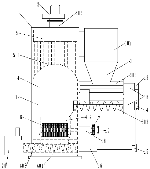
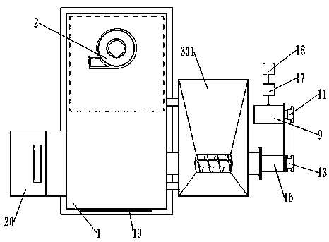
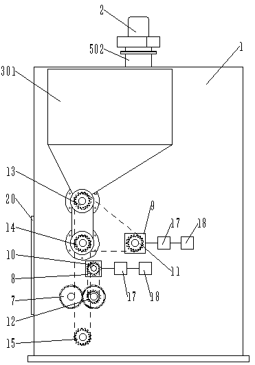
[0028] Such as Figure 1~5 As shown, the biomass particle combustion stove of the present embodiment is mainly composed of a furnace body 1, an induced draft fan 2, a feeding device 3, a storage bin 301, an upper feeding auger 302, a lower feeding auger 303, and a combustion chamber 4. Ash bin 401, ash removal auger 403, flue gas chamber 5, smoke inlet 501, smoke exhaust port 502, combustion bin 402, grate 6, shaft 601, grate teeth 602, gear 7, first motor 8. Second motor 9, first driving wheel 10, second driving wheel 11, first driven wheel 12, second driven wheel 13, third driven wheel 14, fourth driven wheel 15, support sleeve 16, time relay 17 , governor 18, furnace door 19, ash hopper 20 and spacer 21 etc. constitute.

[0029] Wherein the furnace body 1 is provided with a combustion chamber 4 and a flue gas chamber 5, the flue gas c...


PUM


Abstract

The present invention relates to the technical field of combustion equipment, in particular to a biomass particle combustion furnace. A combustion chamber is internally provided with two fire grates,and rotating shafts of the two fire grates respectively extend out of a furnace body and are connected with a fire grate transmission mechanism. An ash clearing auger is arranged in an ash falling bin, and one end of an auger shaft of the ash clearing auger extends out of the furnace body and is connected with an ash clearing transmission mechanism. An ash outlet of the ash clearing auger is arranged on the other side away from the furnace body and a feeding device. A storage bin of the feeding device is arranged at the side upper part of the combustion bin, and the storage bin is arranged above an upper feeding auger. The discharge end of a lower feeding auger is arranged at the side upper part of the combustion bin in the furnace body, and the upper feeding auger and the lower feeding auger are connected with a feeding transmission mechanism. The grate rotating with fixed axis realizes dynamic combustion and solves the slagging problem. The ash removal auger and the synchronous transmission mechanism for feeding and ash removal can solve the problem that accumulated ash cannot be cleaned in time.

Description

technical field [0001] The invention relates to the technical field of combustion equipment, in particular to a biomass particle combustion stove. Background technique [0002] As the country pays more and more attention to environmental protection, and vigorously promotes the development and utilization of biomass energy. Make today's biomass pellet fuel widely used in actual production and life. Biomass pellet fuel has the advantages of easy storage, convenient transportation, clean environmental protection and high combustion efficiency, and is one of the main directions for the development and utilization of biomass energy. [0003] However, there are the following problems when using biological pellets as fuel: [0004] Problem 1: The biomass pellet fuel made of pressed plant stalks has high sugar content, and slagging often occurs in the furnace during combustion. When the fuel burns, slagging in the furnace will block the ventilation gap between the fuel layers, wh...

Claims


Application Information

Patent Timeline
Patent Type & Authority Applications(China)
IPC IPC(8): F23B30/02
Inventor 王丹琪王常军袁顺利王海波刘焕发郑小利陈晓明李会全
Owner 唐山市丰润区神火新能源开发有限公司
Why Eureka
Try Eureka