
Microwave tube permanent magnet focusing system

A technology of permanent magnet focusing and microwave tubes, which is applied in discharge tubes, time-of-flight electron tubes, electrical components, etc., can solve the problems of difficult engineering application of focusing systems and difficult process implementation, and achieves convenient operation and tunable structure Simple, the effect of ensuring a uniform magnetic field

Active Publication Date: 2019-06-07
NO 12 RES INST OF CETC
View PDF6 Cites 4 Cited by
  • Summary
  • Abstract
  • Description
  • Claims
  • Application Information

AI Technical Summary

Problems solved by technology

The smaller the diameter of the electron injection channel, the more difficult it is to implement the process of matching the focusing system and achieving good focusing, which makes the design of the focusing system difficult for engineering applications
Moreover, usually a focus system can only be designed for a certain fixed diameter and length of the electron beam channel, if the focus length of the electron beam changes, the focus system must be redesigned and made

Method used


Image

  • Microwave tube permanent magnet focusing system

Examples


Embodiment 1

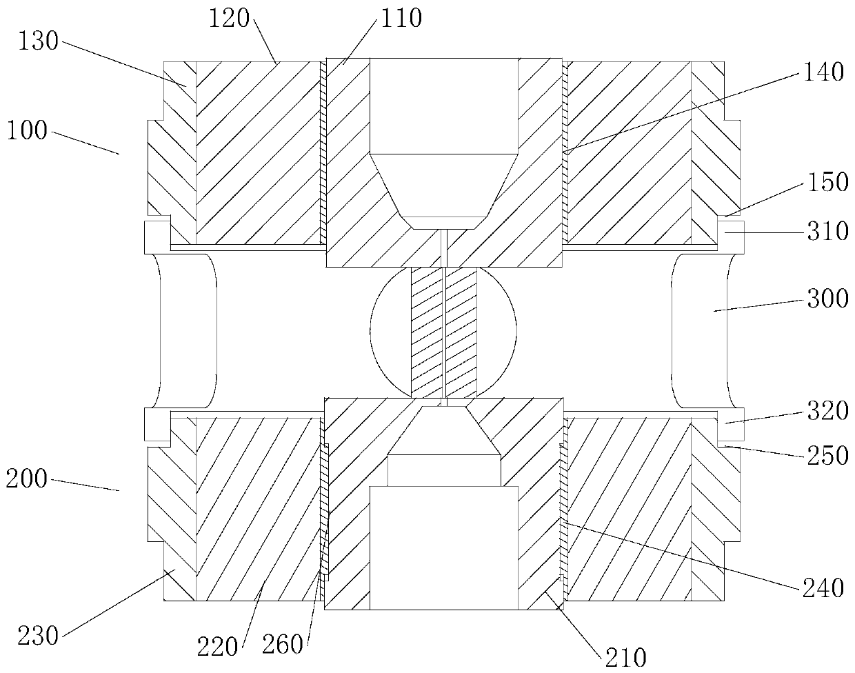
[0029] In the focusing system of the preferred embodiment of the present invention, the focusing system is a permanent magnet focusing system for microwave tubes. The focusing system includes an electron gun permanent magnet assembly, which in turn includes an upper magnetic screen with an opening formed in the center, an upper magnetic ring, and Upper magnetic steel outer ring; collecting pole permanent magnet assembly, which in turn includes a lower magnetic screen with an opening formed in the center, a lower magnetic ring and a lower magnetic steel outer ring, which are arranged between the upper magnetic steel outer ring and the lower magnetic steel outer ring The outer ring transition ring, where the length between the upper magnetic screen and the lower magnetic screen is set to 10mm, the tube diameter of the electron beam channel is 0.3mm, and the ratio of the outer diameter to the inner diameter of the magnetic ring is 1.5:1-3:1; The ratio of the outer diameter to the i...

Embodiment 2

[0031] In the focusing system of another preferred embodiment of the present invention, the focusing system is a permanent magnet focusing system for a klyss traveling wave tube, the focusing system includes an electron gun permanent magnet assembly, and in turn includes an upper magnetic screen with an opening formed in the center , The upper magnetic ring and the upper magnetic steel outer ring; the collecting pole permanent magnet assembly, which in turn includes a lower magnetic screen with an opening formed in the center, a lower magnetic ring and a lower magnetic steel outer ring, arranged on the upper magnetic steel outer ring and the lower magnetic steel The outer ring transition ring between the outer rings, where the length between the upper magnetic screen and the lower magnetic screen is set to 20mm, the tube diameter of the electron injection channel is 0.5mm, and the ratio of the outer diameter to the inner diameter of the magnetic ring is 1.5:1- 3:1; the ratio of ...


PUM


Abstract

The invention discloses a microwave tube permanent magnet focusing system, which comprises an electron gun permanent magnet assembly, a collector permanent magnet assembly and an outer ring transitionring, wherein the electron gun permanent magnet assembly sequentially comprises an upper magnetic screen with an opening formed in the center, an upper magnetic ring and an upper magnetic steel outerring; the collector permanent magnet assembly sequentially comprises a lower magnetic screen with an opening formed in the center, a lower magnetic ring and a lower magnetic steel outer ring, and thelower magnetic ring and the upper magnetic ring have opposite magnetizing directions; and the two end parts of the outer ring transition ring sleeve the upper magnetic steel outer ring and the lowermagnetic steel outer ring, one sides, facing the outer ring transition ring, of the upper magnetic steel outer ring and the lower magnetic steel outer ring comprise an upper matching end surface and alower matching end surface in corresponding match with the end surface of the outer ring transition ring, and in the axial direction of the microwave tube, the distance between the upper matching endsurface and the lower matching end surface is larger than the length of the outer ring transition ring. According to the focusing system disclosed in the invention, tunability of the electron beam focusing length and the magnetic field strength of the microwave tube can be realized, and the electron beams are ensured to be focused in an electron beam channel with the diameter of 0.3 to 0.5 mm andthe length of 10 to 20 nm.

Description

Technical field [0001] The invention relates to the field of microwave tube tooling design, in particular to a microwave tube permanent magnet focusing system. Background technique [0002] Microwave tube is a kind of power amplifier device that uses the interaction of high-speed electron beam and microwave signal to convert the kinetic energy of electron beam into microwave energy. Microwave tubes are widely used in electronic systems such as missile homing, aerospace measurement and control, target imaging, weather detection, electronic countermeasures, and satellite communications, and are the core power components of radar systems. In radar systems, one or several microwave tubes are usually used as the final power amplifier. [0003] The interaction of the microwave tube occurs in the interaction system. The electron beam needs to be focused when passing through the interaction system, otherwise the electron beam will immediately diverge due to the repulsive force between the...

Claims


Application Information

Patent Timeline
Patent Type & Authority Applications(China)
IPC IPC(8): H01J23/087
Inventor 韦莹李冬凤周军杨继涛殷亮窦钺欧阳佳佳
Owner NO 12 RES INST OF CETC
Learn More