
A Method for Reducing Larmor Radius of Electron in Drift Tube

A gyroscopic radius and drift tube technology, applied in the field of beam transmission, can solve the problem that the electron Larmor gyroscopic radius has not been significantly reduced, and achieve the advantages of improving beam interaction efficiency, reducing gyroscopic radius, and suppressing radial oscillation. Effect

Active Publication Date: 2020-11-17
NORTHWEST INST OF NUCLEAR TECH
View PDF3 Cites 0 Cited by
  • Summary
  • Abstract
  • Description
  • Claims
  • Application Information

AI Technical Summary

Problems solved by technology

Yang Jianhua of the National University of Defense Technology adopted a guide magnetic field configuration that gradually decreases through the drift tube region in his doctoral dissertation on low-magnetic field high-power microwave generation devices (Yang Jianhua, National University of Defense Technology doctoral dissertation, 2002), and he believed that the gradually decreasing magnetic field The resulting reduction in the Larmor gyration frequency will reduce the electron's transverse momentum proportionally, but the electron Larmor gyration radius does not decrease significantly

Method used


Image

  • A Method for Reducing Larmor Radius of Electron in Drift Tube
  • A Method for Reducing Larmor Radius of Electron in Drift Tube
  • A Method for Reducing Larmor Radius of Electron in Drift Tube

Examples


Embodiment Construction

[0023] The present invention will be described in detail below in conjunction with the accompanying drawings and embodiments.

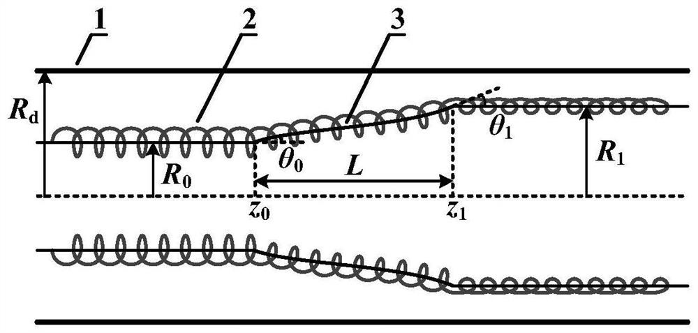
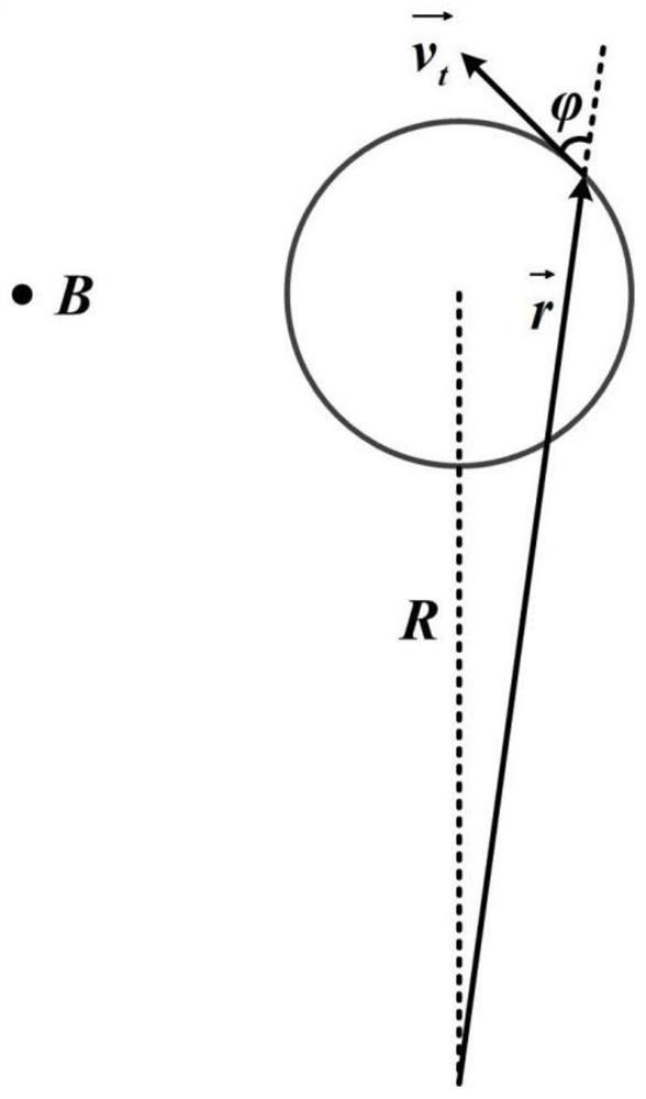
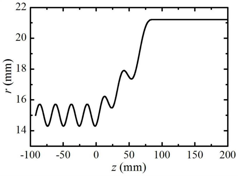
[0024] Such as figure 1 and figure 2 As shown, the parallel gradient magnetic field is loaded in the transition region z in the cylindrical drift tube 0 ≤z≤z 1 In the range, electrons from the uniform axial magnetic field strength is B 0 After the region passes through the transition region parallel to the gradient magnetic field, it enters the axial magnetic field with a strength of B 1 area, B 1 0 , B of the parallel gradient magnetic field in the transition region r The component can realize the transformation of the transverse momentum and axial momentum of the electron. When the electrons enter the parallel gradient magnetic field, the radial velocity is radially outward, and when leaving the parallel gradient magnetic field, the radial velocity is radially inward. The parallel gradient magnetic field reduces the transverse momentum of the...


PUM


Abstract

The present invention provides a method for reduction of an electron Larmor gyration radius in a drift tube. A parallel gradient magnetic field is loaded within a range of z0<=z<=z1 of a transition region in a cylindrical drift tube, electrons are subjected to the parallel gradient magnetic field of the transition region from a region with uniform axial magnetic field intensity B0 and then enter aregion with an axial magnetic field intensity B1, B1<B0, a component Br of the parallel gradient magnetic field of the transition region can achieve conversion of the transverse momentum and the axial momentum of the electrons. When the radial speeds of the electrons are outward in a radial direction when entering the parallel gradient magnetic field, the radial speeds of the electrons are inwardin the radial direction when being far away from the parallel gradient magnetic field, and the effect of parallel gradient magnetic field reduces the transverse momentum of the electrons to inhibit the radial vibration of an electron beam. The method provided by the invention is applied to a low-magnetic field O-type high-power microwave generation device to improve the wave beam interaction efficiency, effectively reduce the bombardment of a device high-frequency structure by the electrons, reduce the risk of vacuum breakdown of the strong electromagnetic field and facilitate efficient and stable operation of the high-power microwave generation device.

Description

technical field [0001] The invention belongs to the field of beam transmission and relates to a method for reducing the Larmor radius of gyration of electrons in a drift tube. Background technique [0002] The transport of electron beams in drift tubes is a fundamental problem for many physical processes. In the O-type high-power microwave generation device, the annular high-current relativistic electron beam generated by the explosive emission cathode is axially transmitted under the confinement of the guiding magnetic field, and the conversion of electron beam energy to microwave energy is completed in the high-frequency structure of the device. When the guiding magnetic field is low, the transverse momentum of the electrons due to the radial electric field causes the electrons to have a larger Larmor radius of gyration when transporting in the drift tube, resulting in significant radial oscillations, which may cause some electrons to bombard the tube wall, Seriously affe...

Claims


Application Information

Patent Timeline
Patent Type & Authority Patents(China)
IPC IPC(8): H01J25/10H01J23/10
Inventor 孙钧张广帅吴平史彦超曹亦兵谭维兵
Owner NORTHWEST INST OF NUCLEAR TECH
Learn More