
Linear charging system, and constant current and constant voltage control circuit and voltage following control method thereof

A constant current and constant voltage control and voltage following technology, which is applied to battery circuit devices, circuit devices, collectors, etc., can solve the problems of low voltage following precision and frequent chip restarts, and achieve the effect of simplifying the circuit

Pending Publication Date: 2019-06-07
SHANGHAI NATLINEAR ELECTRONICS CO LTD
View PDF0 Cites 12 Cited by
  • Summary
  • Abstract
  • Description
  • Claims
  • Application Information

AI Technical Summary

Problems solved by technology

[0005] In view of the above-mentioned shortcomings of the prior art, the object of the present invention is to provide a linear charging system, a constant current and constant voltage control circuit and its voltage following control method, which are used to solve the problem of frequent restarts of the constant current and constant voltage control chip in the prior art. , Low voltage following accuracy, etc.

Method used


Image

  • Linear charging system, and constant current and constant voltage control circuit and voltage following control method thereof
  • Linear charging system, and constant current and constant voltage control circuit and voltage following control method thereof
  • Linear charging system, and constant current and constant voltage control circuit and voltage following control method thereof

Examples


Embodiment 1

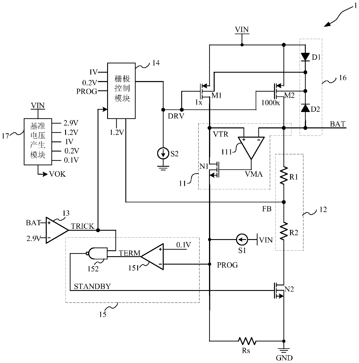
[0060] Such as figure 2 As shown, this embodiment provides a constant current and constant voltage control circuit 1, and the constant current and constant voltage control circuit 1 includes:

[0061] Current sampling tube M1 , output power tube M2 , voltage following control module 11 , output voltage sampling module 12 , constant current calibration point selection module 13 and gate control module 14 .

[0062] Such as figure 2 As shown, the source of the current sampling tube M1 is connected to the input power supply VIN, the gate is connected to the output terminal of the gate control module 14, and the drain is connected to the first end of the sampling resistor Rs after passing through the voltage following control module 11 , the second end of the sampling resistor Rs is grounded to GND, and the current sampling tube M1 is used to generate a sampling current.

[0063] Specifically, in this embodiment, the current sampling tube M1 is a P-type transistor, including b...

Embodiment 2

[0099] Such as Figure 4 As shown, this embodiment provides a linear charging system 01, and the linear charging system 01 includes:

[0100] The constant current and constant voltage control circuit 1 , the power input circuit 2 and the battery module 3 of the first embodiment.

[0101] Such as Figure 4 As shown, the constant current and constant voltage control circuit 1 is used to realize constant current and constant voltage control, thereby obtaining a stable output. In this embodiment, the constant current and constant voltage control circuit 1 forms a chip. In order to improve the flexibility of the constant current and constant voltage control circuit 1, the sampling resistor Rs is set outside the chip. The sampling resistor Rs realizes the setting of the output current. For the specific structure and connection relationship of the constant current and constant voltage control circuit 1 , please refer to the description of the first embodiment, and details will not...


PUM


Abstract

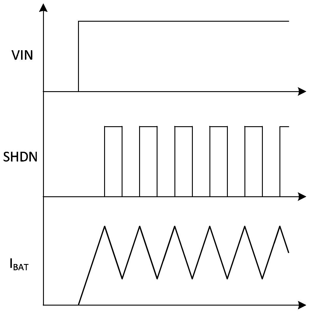
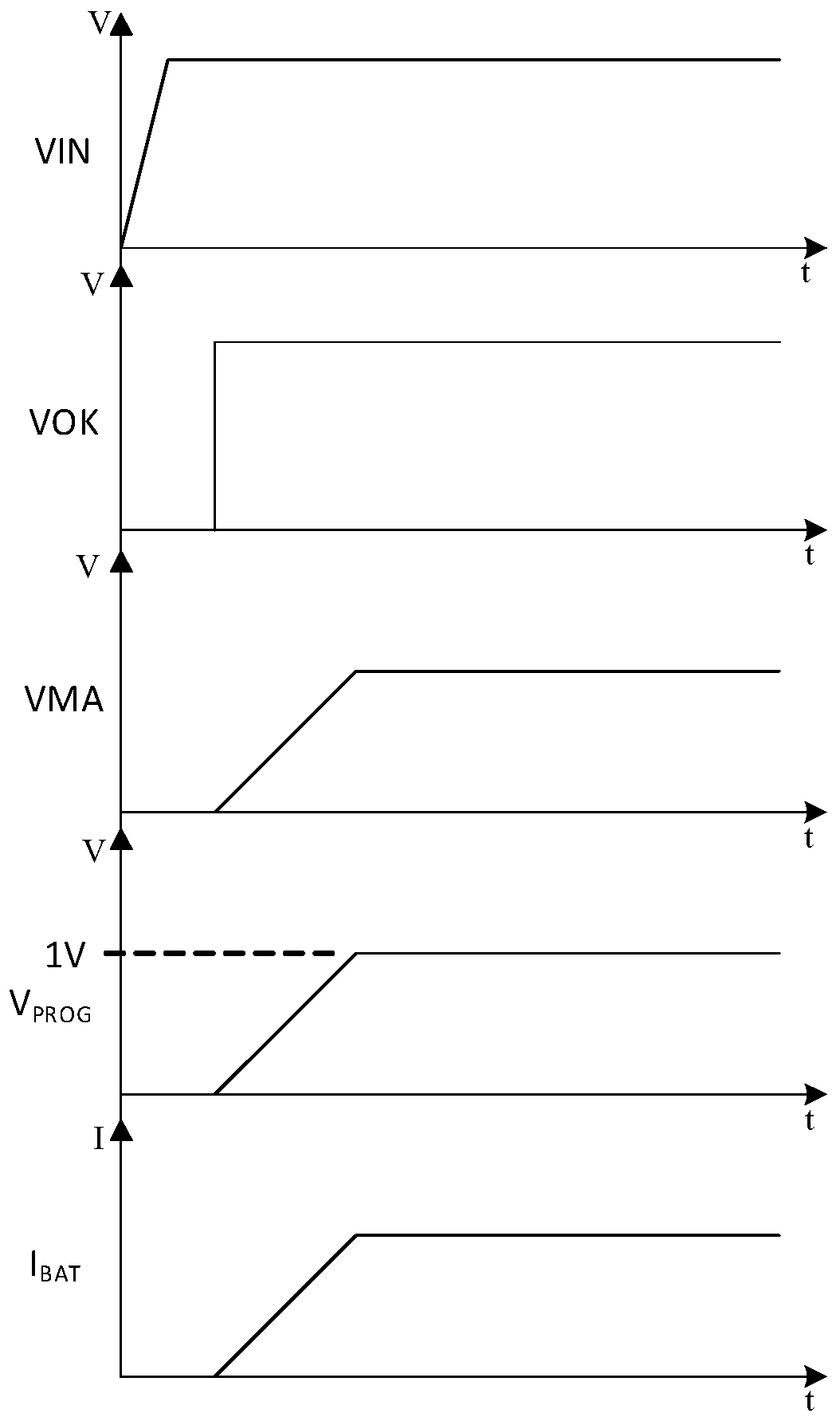
The present invention provides a linear charging system, and a constant current and constant voltage control circuit and a voltage following control method thereof. The linear charging system comprises a constant current and constant voltage control circuit, a power supply input circuit for power supply and a battery module for energy storage. The constant current and constant voltage control circuit comprises a current sampling tube, an output power tube, a control current sampling tube, a voltage following control module having the same drain voltage as the output power tube, and a gate control module configured to regulate the gate voltage of the current sampling tube and the output power tube based on the voltage sampling feedback signals and the current sampling feedback signals. Thelinear charging system, and the constant current and constant voltage control circuit and the voltage following control method thereof perform linear control of impedance of an N-type regulate transistor connected in series with a current sampling branch without starting current overshooting so as to solve the problem of current overshooting when the linear charging management is started and evencontinuous restart caused by the current overshooting and simplify part of the circuit; and moreover, the output current can still maintain the high-precision current magnification times when the output voltage is low.

Description

technical field [0001] The invention relates to the field of integrated circuit design and application, in particular to a linear charging system, a constant current and constant voltage control circuit and a voltage following control method thereof. Background technique [0002] Over the years, various linear charging management ICs (integrated circuits) have been developed and widely used to realize the control of constant current and constant voltage output in battery charging, and are used in battery management of various portable devices. [0003] In the prior art, the drain of the current sampling tube is consistent with the drain voltage of the output power tube by controlling the impedance and voltage drop of the P tube. However, when the gate voltage of the P tube is at a low level, the P tube is turned on. Risk of current overshoot. Therefore, anti-overshoot protection will be added in the prior art, for example, when the voltage at the current setting terminal is...

Claims


Application Information

Patent Timeline
Patent Type & Authority Applications(China)
IPC IPC(8): H02J7/00
Inventor 班福奎
Owner SHANGHAI NATLINEAR ELECTRONICS CO LTD
Learn More