
System and method for position sensor error compensation of permanent magnet synchronous motor

A permanent magnet synchronous motor and error compensation technology, applied in the field of error compensation, can solve problems such as control stability deterioration, power loss, noise increase, etc., to improve control accuracy and stability, improve power loss and noise, and compensate for accuracy errors. Effect

Active Publication Date: 2021-04-06
CHINA FIRST AUTOMOBILE
View PDF7 Cites 0 Cited by
  • Summary
  • Abstract
  • Description
  • Claims
  • Application Information

AI Technical Summary

Problems solved by technology

[0004] In order to improve the deterioration of control stability and the phenomenon of power loss and noise increase caused by errors in position information reported by position sensors such as permanent magnet synchronous motor resolvers, the present invention provides a permanent magnet synchronous motor position sensor error compensation system and method. It can effectively compensate the accuracy error caused by various reasons of the position sensor of the permanent magnet synchronous motor, improve the control accuracy and stability of the permanent magnet synchronous motor, and effectively improve the operating power loss and noise of the permanent magnet synchronous motor

Method used


Image

  • System and method for position sensor error compensation of permanent magnet synchronous motor
  • System and method for position sensor error compensation of permanent magnet synchronous motor
  • System and method for position sensor error compensation of permanent magnet synchronous motor

Examples


Embodiment Construction

[0031] In order to make the technical problems, technical solutions and advantages to be solved by the present invention clearer, the following will describe in detail with reference to the drawings and specific embodiments.

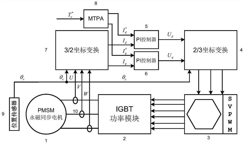
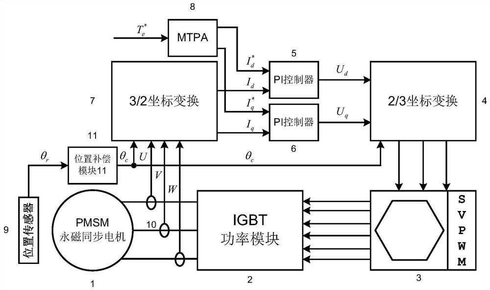
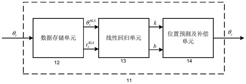
[0032] figure 1 It is a schematic diagram of the overall control system of the existing permanent magnet synchronous motor; figure 2 A schematic structural diagram of a permanent magnet synchronous motor position sensor error compensation system provided by an embodiment of the present invention; image 3 is the internal structure diagram of the data storage unit; Figure 4 It is a diagram of the internal structure of the linear regression unit.

[0033] The existing permanent magnet synchronous motor overall control system such as figure 1 shown. Such as figure 1 As shown, the control strategy of the system is: the permanent magnet synchronous motor 1 generates three-phase current, the three-phase current sensor 10 detects the three-phase current ...


PUM


Abstract

The invention provides a position sensor error compensation system of a permanent magnet synchronous motor, which is used for compensating the rotor position of the permanent magnet synchronous motor. The invention also provides an error compensation method for the position sensor of the permanent magnet synchronous motor. The permanent magnet synchronous motor position sensor error compensation system and method provided by the present invention use the data including the rotor position and the corresponding time to fit the rotor position at each compensation, and then use the corresponding relative time and this time The fitted linear equation calculates the compensated rotor position. Since the data of multiple calculation cycles are fused, it can effectively compensate the accuracy error of the permanent magnet synchronous motor position sensor due to various reasons, and improve the control of the permanent magnet synchronous motor. Accuracy and stability, effectively reducing the power loss and noise of permanent magnet synchronous motor operation.

Description

technical field [0001] The invention relates to an error compensation method, in particular to a permanent magnet synchronous motor position sensor error compensation system and method. Background technique [0002] Pure electric vehicles and hybrid vehicles will become the main forms of future vehicles due to their low pollution and emissions and high fuel economy. The power of pure electric vehicles and hybrid vehicles mainly uses permanent magnet synchronous motors, which are generally equipped with position sensor devices such as resolvers. The motor rotor position detected and decoded by the sensor will have certain errors. The rotor position error of the permanent magnet synchronous motor will affect the control accuracy, increase the current and torque fluctuation amplitude, increase the power loss of the motor, increase the noise content of the motor, and even seriously affect the motor control effect or even lose control. [0003] Therefore, there is an urgent nee...

Claims


Application Information

Patent Timeline
Patent Type & Authority Patents(China)
IPC IPC(8): H02P21/14H02P21/18
Inventor 王飞李岩李帅陈晓娇李伟亮文彦东
Owner CHINA FIRST AUTOMOBILE
Learn More