

Fabric over foam and manufacturing method thereof
A conductive pad and conductive layer technology, applied in the direction of electrical components, magnetic field/electric field shielding, etc., can solve the problems of inconvenient operation, easy wrinkles on the appearance of conductive cloth, and cracking of the coating mouth, so as to solve the problem of limited working height Effect
Pending Publication Date: 2019-06-07
常州市飞荣达电子材料有限公司
View PDF2 Cites 3 Cited by
- Summary
- Abstract
- Description
- Claims
- Application Information
AI Technical Summary
Problems solved by technology
[0004] The existing conductive pads have the following deficiencies: 1. The current technology for preparing conductive cloth is limited, and the thinnest limit thickness is 0.03 mm, which limits the final thickness of the finished conductive pad and cannot be used at extremely low working heights; 2. 1. During the preparation process of the conductive cloth, due to the great influence of the production process and human operation, the appearance of the conductive cloth is prone to wrinkles, which affects the compression resistance of the finished conductive pad; 3. The density of the foam is difficult to control. The compression and rebound stress of the final conductive gasket is difficult to control; 4. During the process of wrapping the foam with conductive cloth, the bonding track is prone to shift, and the final conductive gasket is compressed. If it is blocked, the electronic device cannot be used normally; 5. When the conductive gasket is installed, it is usually installed inside the electronic device by bonding, which is inconvenient to operate and easy to fall off, which eventually leads to failure of the electronic device; 6. It cannot pass through the backflow Soldering process for automatic surface mounting, low installation efficiency
Method used
View moreImage
Smart ImageViewing Examples

Examples
Embodiment 1
[0076] Make a conductive pad with a size of 4mm*4mm*25mm: metallized PI film+adhesive layer+foam
Embodiment 2
[0083] Make a conductive gasket with a size of 4mm*4mm*25mm: metallized PI film+adhesive layer+rubber
Embodiment 3
[0090] Make a conductive pad with a size of 4mm*4mm*25mm: metallized PI film+adhesive layer+silica gel
Login to View More PUM
 Abstract
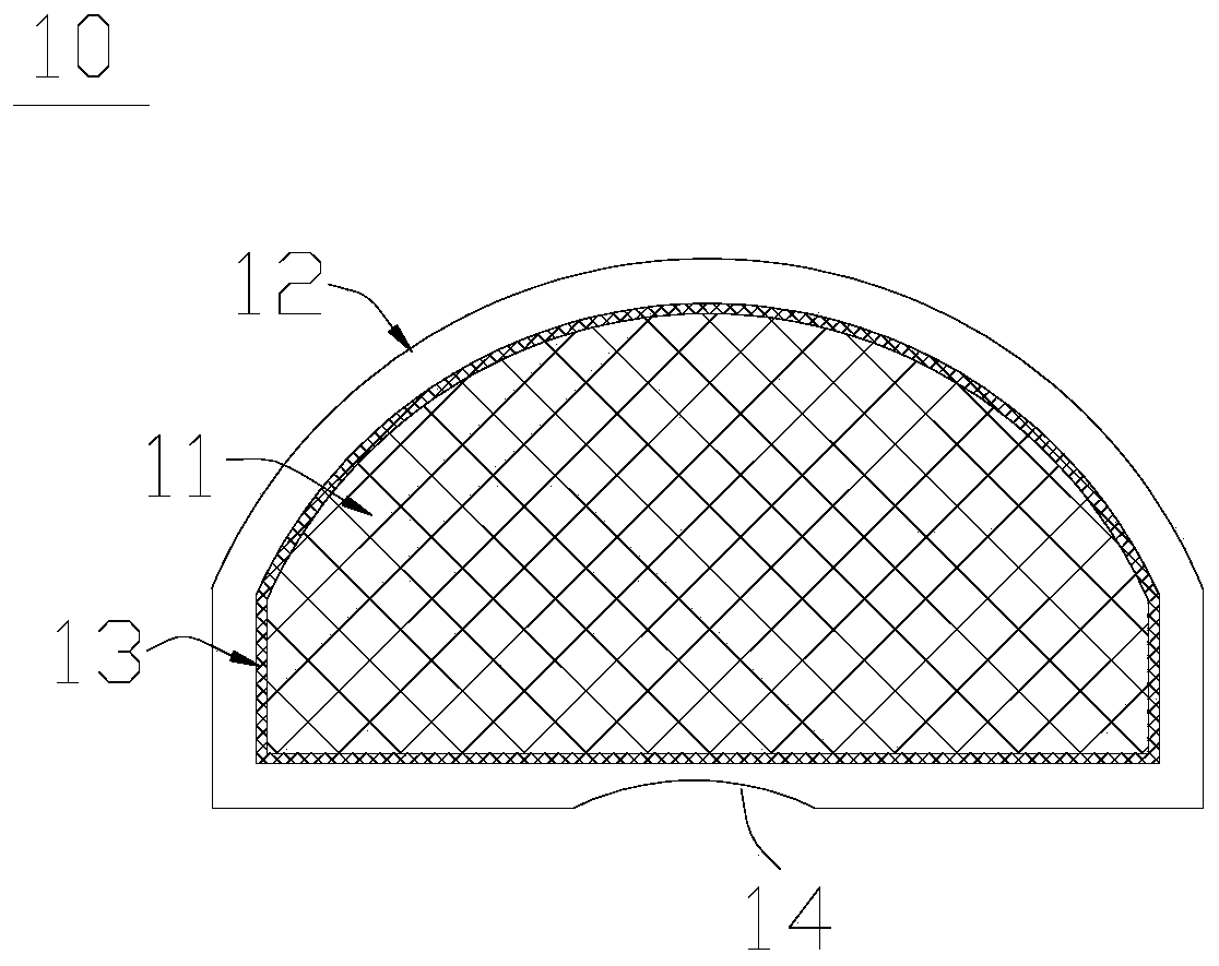
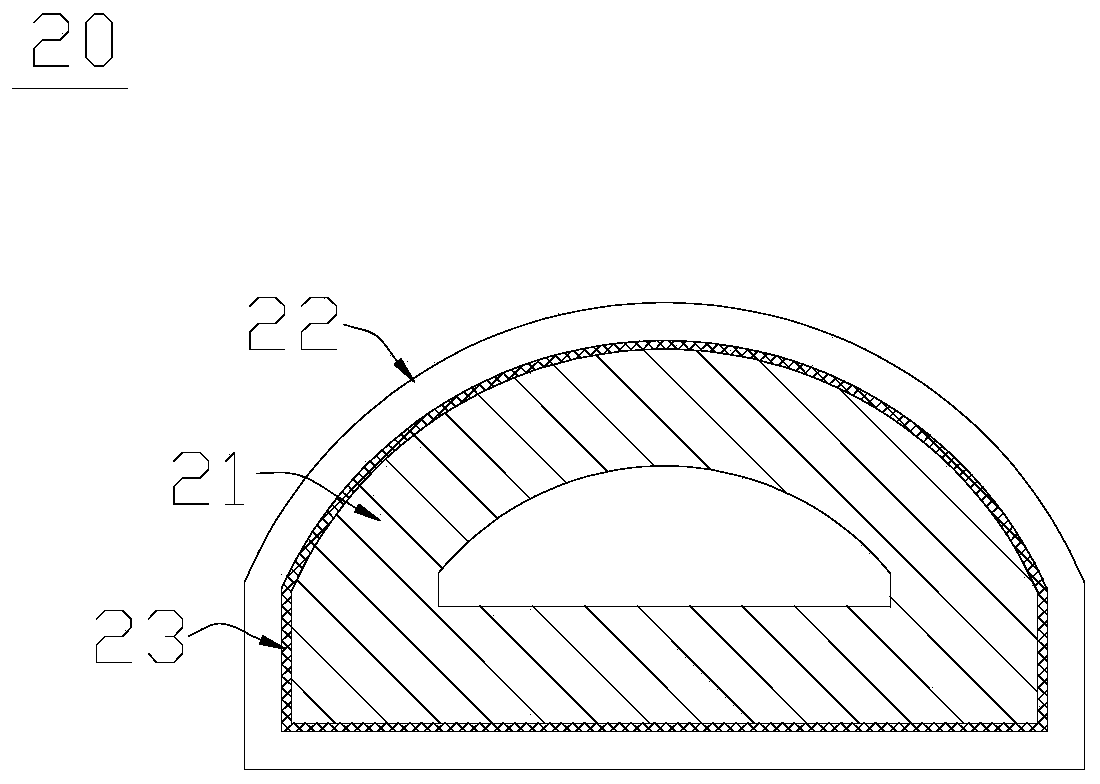
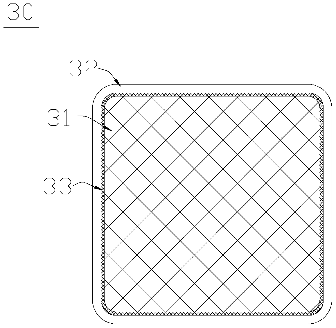
The invention discloses a fabric over foam and a manufacturing method thereof. The fabric over foam comprises an elastic core, a solderable conductive layer and a bonding layer. The outer surface of the elastic core is coated with the solderable conductive layer, the bonding layer is arranged between the solderable conductive layer and the elastic core, and the solderable conductive layer can be bonded on the elastic core. The fabric over foam coats and is fixed on the elastic core in a bonding mode to form a fabric over foam capable of reflow soldering or SMT, the solderable conductive layercan achieve that the fabric over foam is installed on an electronic device in a reflow soldering mode and is used for the reflow soldering surface installation technology so as to solve the problems of limited operation height, the production process, the human influence and quality risk in a traditional fabric over foam.
Description
technical field [0001] The invention relates to a conductive gasket, in particular to a conductive gasket and a manufacturing method thereof. Background technique [0002] Electromagnetic waves can be emitted from the circuits of electronic devices through the atmosphere or transmitted through wires. Various electromagnetic waves generated by the circuits of electronic equipment will cause electromagnetic interference, which may reduce the performance of peripheral electronic equipment, cause noise in electronic equipment, damage electronic imaging, reduce the service life of electronic equipment, etc., and eventually cause electronic equipment to fail and cannot be used. . In addition, electromagnetic interference may also cause adverse effects on the human body and the natural environment. [0003] In electronics, communications, medical and other related fields, various filling materials with electromagnetic interference shielding are usually used to fill the gaps insid...
Claims
Login to View More Application Information
Patent Timeline
 Patent Type & Authority Applications(China)
IPC IPC(8): H05K9/00
Inventor 曾晓辉严意宏黎凯强黄志明余学武吴剑飞
Owner 常州市飞荣达电子材料有限公司