Plastering, galling and automatic mortar-spraying machine

An automatic and spraying technology for ash brushing, which is applied in construction and building construction, etc., can solve problems such as inability to paint high walls, and achieve the effect of reducing labor amount, labor cost, and improving plastering efficiency.

Active Publication Date: 2019-06-11
CHINA CONSTR SECOND ENG BUREAU LTD
View PDF10 Cites 12 Cited by
  • Summary
  • Abstract
  • Description
  • Claims
  • Application Information

AI Technical Summary

Problems solved by technology

[0007] In order to solve the problems existing in the prior art, the present invention provides an automatic spraying machine for plastering and roughening, which has three functions of plastering, roughening and spraying, and has the advantages of high slurrying efficiency and horizontal moving plastering, which solves the problem of Problems such as inability to paint higher walls

Method used


Image

  • Plastering, galling and automatic mortar-spraying machine
  • Plastering, galling and automatic mortar-spraying machine
  • Plastering, galling and automatic mortar-spraying machine

Examples


Embodiment 1

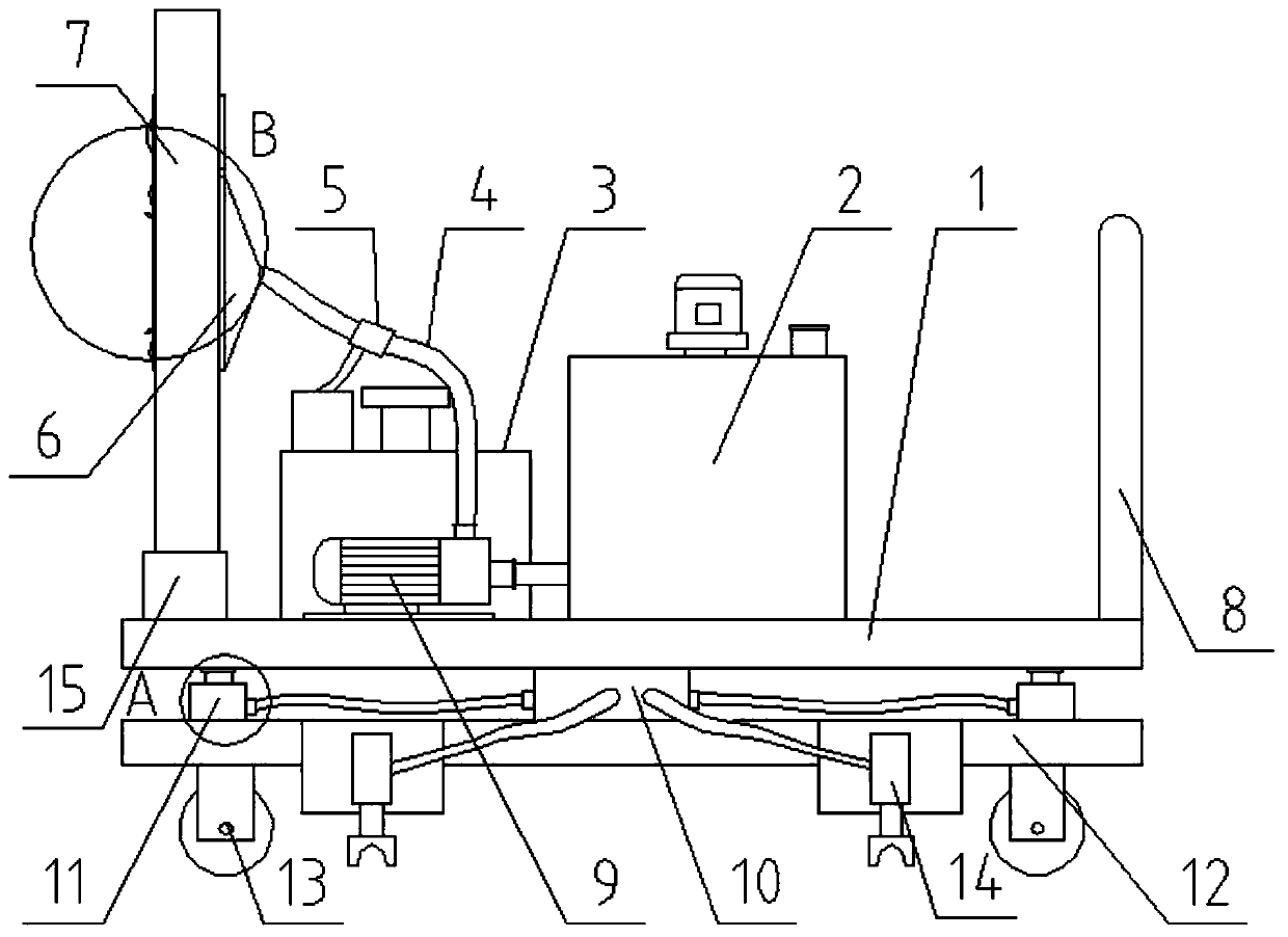
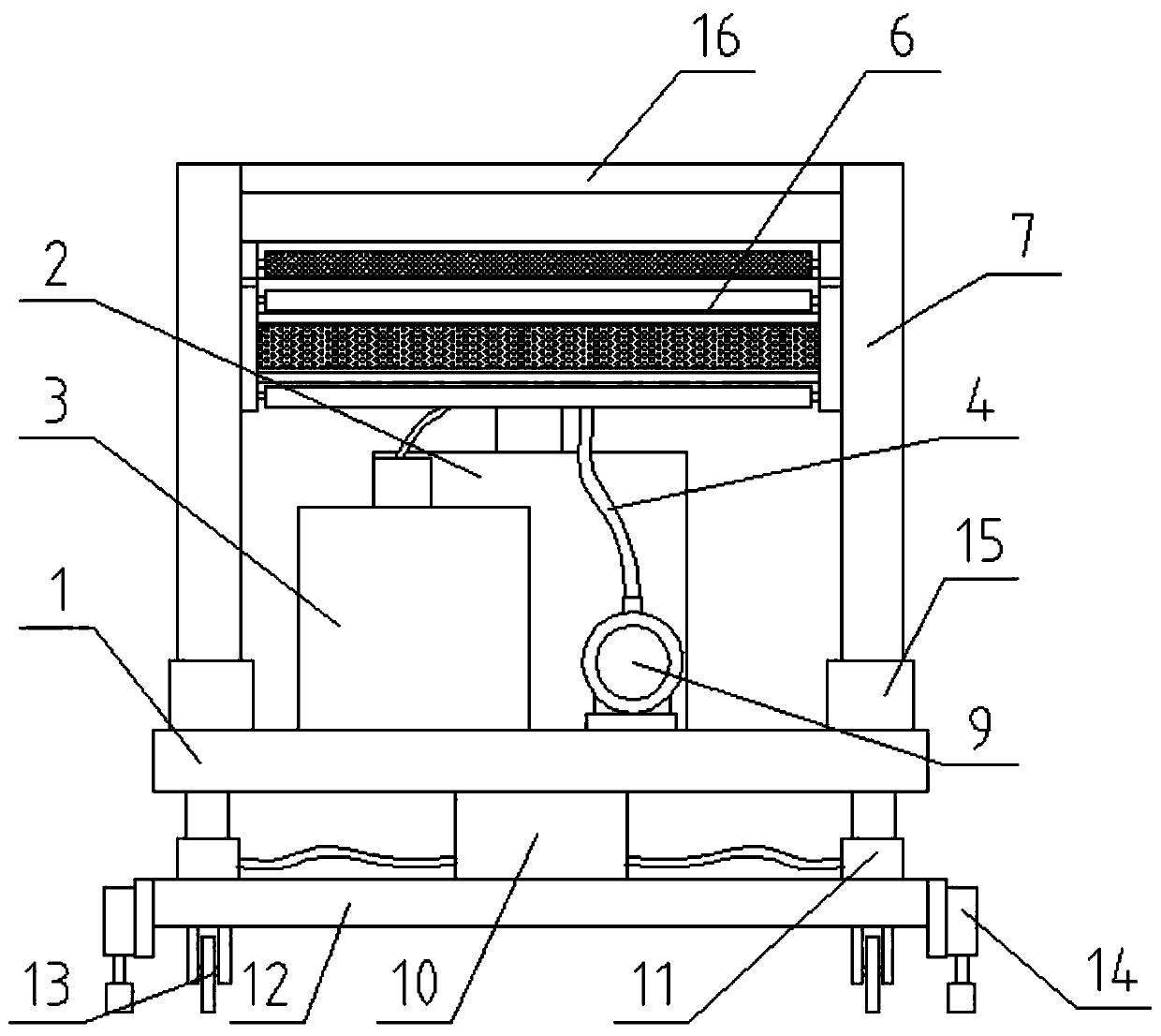
[0044] Such as Figure 1-10 As shown, a plastering and napping automatic spraying machine includes a base plate 1 and a base plate 12 located below the base plate 1, a hydraulic oil tank 10 is fixedly installed between the base plate 1 and the base plate 12 and is located at Four hydraulic jacking devices 11 at the four corners of the base plate 12, the base plate 1 and the base plate 12 are connected through four hydraulic jacking devices 11, and the four hydraulic jacking devices 11 all pass through the hydraulic oil tank 10 The oil guide pipe is connected, and the horizontal displacement mechanism 14 is symmetrically installed on the side of the base plate 12. The horizontal displacement mechanism 14 communicates with the hydraulic oil tank 10 through the oil guide pipe, and the four corners of the lower end of the base plate 12 are equipped with rollers 13.

[0045] The upper surface of the base plate 1 is fixedly equipped with a push-pull handle 8, a slurry storage box 2,...

Embodiment 2

[0052] Such as Figure 12 As shown, in this embodiment, on the basis of Embodiment 1, a handle cover 43 is fixedly installed on the push-pull handle 8, and a finger groove is provided on the handle cover 43, which is beneficial to promote the device to move more easily and conveniently. The constructor's hands provide some protection.

[0053] The rest of the structure and working principle of embodiment 2 are the same as embodiment 1.

Embodiment 3

[0055] Such as Figure 13 As shown, in this embodiment, on the basis of Embodiment 1, a stirring motor 20 and a feed inlet 21 are fixedly installed on the top of the pulp storage box 2, and the output end of the stirring motor 20 extends downward to the interior of the pulp storage box 2 And the stirring rod 19 is coaxially connected, which is beneficial to drive the stirring rod 19 to stir the slurry evenly through the stirring motor 20, so as to ensure the construction efficiency, and the feeding port 21 is convenient for putting in the slurry.

[0056] The rest of the structure and working principle of embodiment 3 are the same as embodiment 1.


PUM


Abstract

The invention discloses a plastering, galling and automatic mortar-spraying machine, which comprises a pedestal plate and a base plate located below the pedestal plate, a hydraulic oil tank and a plurality of hydraulic jacking devices located at the four corners of the base plate are fixedly mounted between the pedestal plate and the base plate, the pedestal plate and the base plate are connectedthrough the multiple hydraulic jacking devices, the multiple hydraulic jacking devices all communicate with the hydraulic oil tank through oil guiding pipes correspondingly, horizontal displacement mechanisms are symmetrically mounted on the side faces of the base plate and communicate with the hydraulic oil tank through oil guiding pipes, and idler wheels are mounted at the four corners of the lower end of the base plate. The plastering, galling and automatic mortar-spraying machine has the three functions of plastering, galling and mortar spraying and has the advantages of high mortar-outletefficiency and horizontal moving plastering, and the problem that the high wall surface cannot be painted is solved.

Description

technical field [0001] The invention relates to the technical field of construction, in particular to an automatic spraying machine for plastering and napping. Background technique [0002] In the process of house construction, when the overall structure is completed, a layer of plaster needs to be applied on the surface of the wall. The surface of the building wall is plastered by smoothing the mortar onto the surface of the building wall to form a layer of plaster on the surface of the wall. The plaster layer formed has three main functions: [0003] (1) Satisfy the functional requirements of use, and the plaster layer can play the role of heat preservation, heat insulation, moisture resistance, weather resistance and sound insulation; [0004] (2) To meet the aesthetic requirements, the plastering layer can make the interface of the building smooth, clean, beautiful and comfortable, and it is beneficial to the next process such as tiling or putty; [0005] (3) To protec...

Claims


Application Information

Patent Timeline
Patent Type & Authority Applications(China)
IPC IPC(8): E04F21/08
Inventor 柏寒阳徐磊刘博王大林姚兴树曹建军
Owner CHINA CONSTR SECOND ENG BUREAU LTD
Why Eureka
Try Eureka