
Sulfur separating and discharging device for high-sulfur gas field

A high-sulfur gas field technology, applied in the direction of loading/unloading, transportation and packaging, mining fluids, etc., can solve the problems of reducing the effective flow area of ​​pipelines, complex pipeline networks, and blockage of downstream gathering and transportation pipelines, so as to eliminate the risk of natural gas poisoning , safe and convenient operation, and simple device structure

Inactive Publication Date: 2019-06-11
CHINA UNIV OF PETROLEUM (EAST CHINA)
View PDF6 Cites 1 Cited by
  • Summary
  • Abstract
  • Description
  • Claims
  • Application Information

AI Technical Summary

Problems solved by technology

[0003] (1) The equipment and pipeline network of the gathering and transportation station are complex, and elemental sulfur is easily deposited on the throttle orifice, tee, etc., which seriously affects the safe operation of the equipment
[0004] (2) Blocking the downstream gathering and transportation pipeline, resulting in a decrease in the efficiency of the gathering and transportation pipeline
In the process of gathering and transportation, as the temperature and pressure drop, the solubility of natural gas to sulfur will decrease, and sulfur will be precipitated, which will deposit on the pipe wall, reduce the effective flow area of ​​the pipe, and increase the energy consumption of transportation. , the accumulation of sulfur crystals can block fluid passages and lead to well shut-in and shutdown
[0005] (3) Increase the risk of corrosion in the gathering and transportation system
This method affects normal production, the labor intensity of the staff is high, there is a risk of poisoning, and safety is difficult to guarantee

Method used


Image

  • Sulfur separating and discharging device for high-sulfur gas field
  • Sulfur separating and discharging device for high-sulfur gas field
  • Sulfur separating and discharging device for high-sulfur gas field

Examples


Embodiment Construction

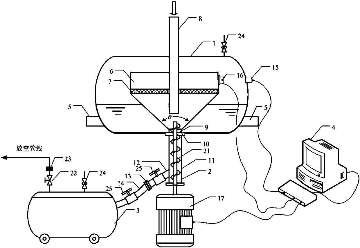
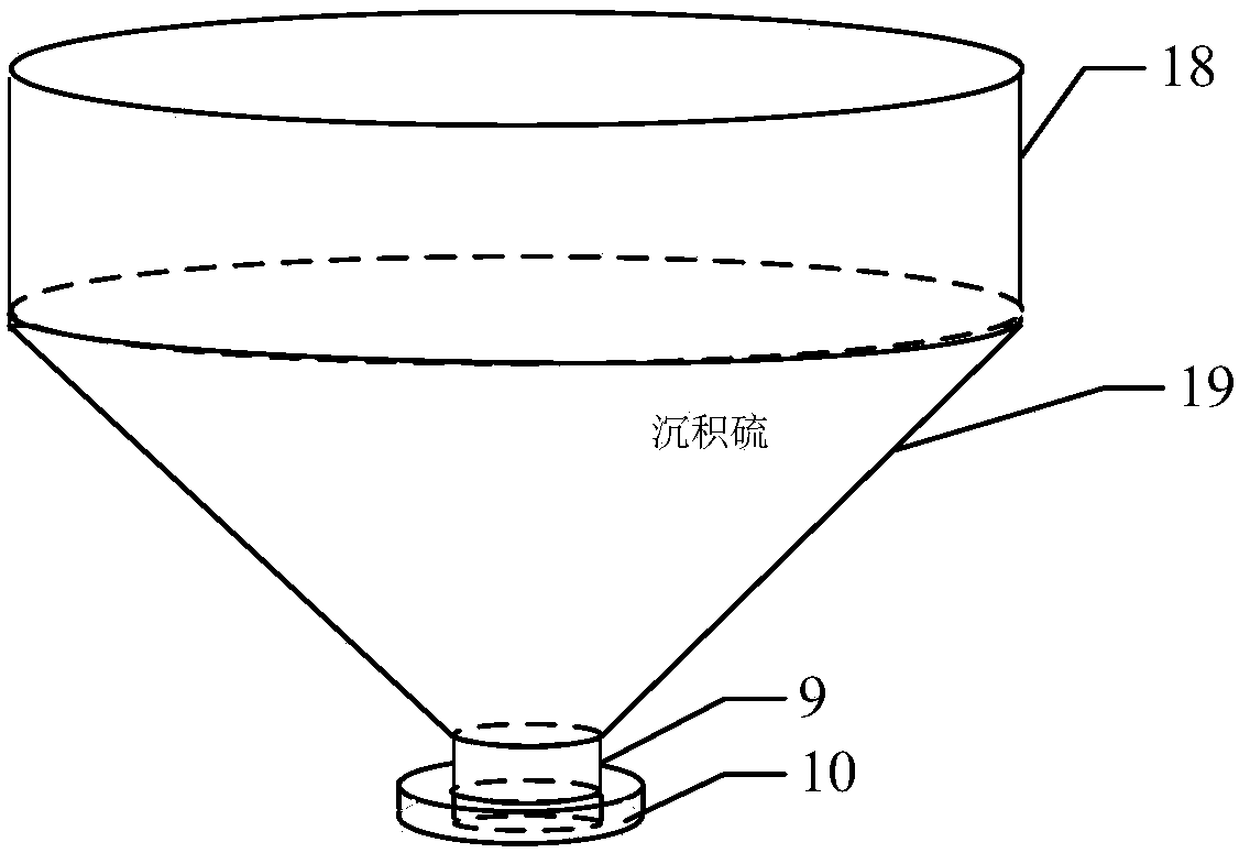
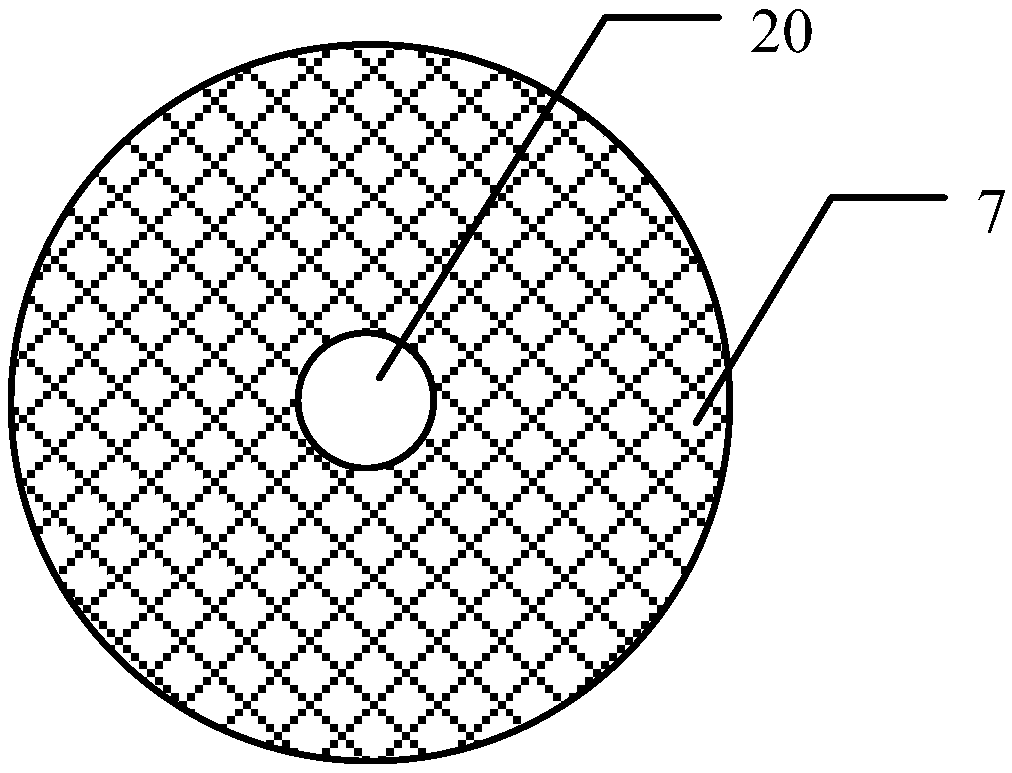
[0025] like figure 1 As shown, a sulfur separation and desulfurization device for a high-sulfur gas field is characterized in that it mainly includes a liquid-solid separation tank 1, a screw sulfur conveyer 2, a sulfur tank truck 3, and a data acquisition control module 4. The liquid-solid separation tank 1 is a horizontal Type high-pressure vessel, the left and right ends of the liquid-solid separation tank 1 are respectively provided with a drain pipe 5 near the bottom, the inside of the liquid-solid separation tank is provided with a sulfur accumulating chamber 6, and the sulfur accumulating chamber 6 is provided with a sulfur barrier 7, and the inlet of the sulfur-water mixture The pipe 8 passes through the guide hole 20 of the sulfur barrier 7 from the top of the liquid-solid separation tank to the inside of the sulfur accumulating chamber 6, and the sulfur outlet 9 at the bottom of the sulfur accumulating chamber 6 is transported through the connecting flange 10 and the ...


PUM

PropertyMeasurementUnit
Cone angleaaaaaaaaaa

Abstract

The invention relates to a sulfur separating and discharging device for a high-sulfur gas field. The sulfur separating and discharging device mainly comprises a liquid-solid separation tank, a spiralsulfur transporting device, a sulfur tank truck and a data acquisition control module. After a sulfur and water mixture enters a sulfur deposition chamber, natural settlement and separation are performed by relying on the water and sulfur density difference, and a sulfur isolating grid is used for preventing sulfur deposition particles from entering a water phase. The data acquisition control module monitors the height of sulfur deposition at all times. When the thickness of the sulfur deposition reaches a critical value, a motor of the spiral sulfur transporting device drives a spiral blade to rotate, and the sulfur particles are continuously transported downwards with the rotation of the blade under the action of centrifugal force and friction force and enter the sulfur tank truck through a sulfur discharging tube. Compared with the prior art, the operation of a separator of does not need to be stopped in the process of discharging sulfur, normal production is not affected, full sealing, high safety, uniform sulfur discharging speeds, a simple device structure, low construction cost and low maintenance cost are achieved, and the sulfur separating and discharging device has broadapplication prospects.

Description

Technical field: [0001] The invention relates to a sulfur separation and desulfurization device for a high-sulfur gas field, in particular to a device for separating deposited sulfur and produced water in a high-sulfur gas field, and discharging the separated sulfur out of a separator, which belongs to high-sulfur natural gas production area. Background technique: [0002] In sour gas fields with high sulfur content, elemental sulfur dissolves in sour natural gas in the form of polysulfides. When the gas well is exploited, the amount of dissolved elemental sulfur in the gas will also decrease due to the decrease in temperature and pressure, and the supersaturated sulfur It will be precipitated in the gathering and transportation system, and then deposited. Sulfur deposition is a huge hazard, mainly reflected in the following aspects: [0003] (1) The equipment and pipe network of the gathering and transportation station are complicated, and elemental sulfur is easily depos...

Claims


Application Information

Patent Timeline
IPC IPC(8): E21B43/34B65G65/46
Inventor 梁法春尚德斌莫琼高继峰李明和韩璐媛杭越
Owner CHINA UNIV OF PETROLEUM (EAST CHINA)
Learn More