Planar array self-adaptive beam forming coupling self-correction method based on auxiliary array elements

An adaptive beam and planar array technology, which is applied in the directions of radio wave director parts and direction finders using radio waves, etc., can solve problems such as high application conditions, difficulty in meeting actual scene requirements, and application direction restrictions.

Inactive Publication Date: 2019-06-11
HARBIN ENG UNIV
View PDF3 Cites 2 Cited by
  • Summary
  • Abstract
  • Description
  • Claims
  • Application Information

AI Technical Summary

Problems solved by technology

However, these methods or application conditions have high requirements, or are limite

Method used


Image

  • Planar array self-adaptive beam forming coupling self-correction method based on auxiliary array elements
  • Planar array self-adaptive beam forming coupling self-correction method based on auxiliary array elements
  • Planar array self-adaptive beam forming coupling self-correction method based on auxiliary array elements

Examples


Embodiment 1

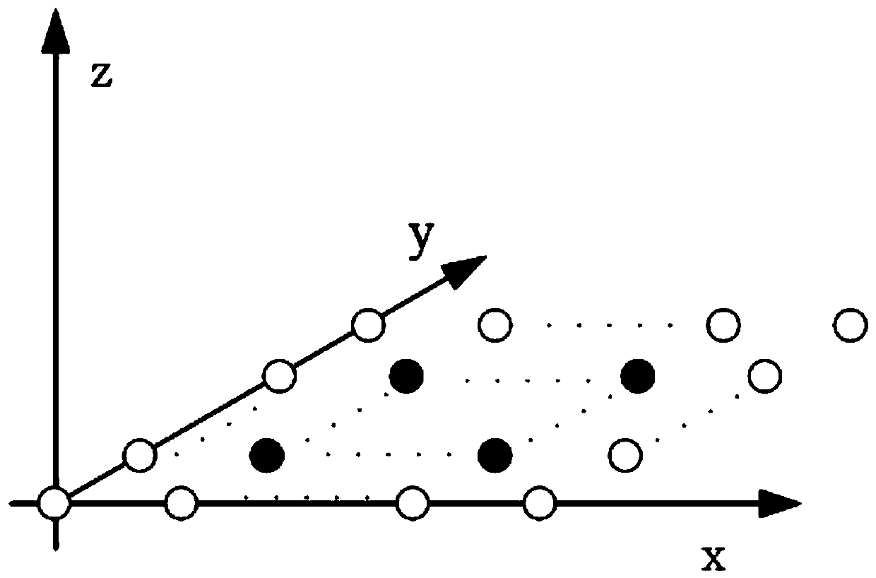
[0051] according to Figure 1 to Figure 6 , a planar array adaptive beamforming coupling self-correction method based on auxiliary array elements, including the following steps:

[0052] Step 1: According to the arrangement of the actual planar array elements, set auxiliary array elements around it and keep the original planar array, such as figure 1 shown.

[0053] Step 2: If it is assumed that there are K plane wave signals incident on this planar antenna array, and these incident signals are independent of each other, and their arrival angles are all different, for the received signal vector for:

[0054]

[0055] Among them, P is the selection matrix, C is the antenna array mutual coupling matrix, is the antenna array direction vector matrix, θ i is the azimuth angle, φ i is the pitch angle, where (i=1,2,...,K), s(n)=[s 1 (n),...,s K (n)] T is the signal vector, n(n) is the noise, where P is:

[0056]

[0057] O is a (N-2)×N-dimensional zero matrix, and J ...


PUM


Abstract

The invention discloses a planar array self-adaptive beam forming coupling self-correction method based on auxiliary array elements, and belongs to the technical field of array beam forming. The method comprises the following steps of firstly, constructing a physical model of a required auxiliary array element according to an actual array element; secondly, obtaining a receiving signal vector of the middle actual array element according to the physical model after the auxiliary array element is arranged; thirdly, correcting a guiding vector of a middle sub-array to obtain a corrected guiding vector; and finally, solving weight formed by self-adaptive beam forming according to a linearly constraint minimum variance criterion in combination with a lagrangian multiplier method, and realizingdecoupling self-correction of a planar array antenna. The method is suitable for decoupling of the planar array, and coupling self-correction can be carried out under a condition of an unknown mutualcoupling matrix; the planar array with the coupling phenomenon exists, the antenna array can generate accurate main lobe and null steering directions through coupling self-correction, the null steering depth is enough to meet the suppression of interference signals, and a minor lobe is low.

Description

technical field [0001] The invention relates to the technical field of array beamforming, in particular to a coupling self-calibration method for adaptive beamforming of a planar array based on auxiliary array elements. Background technique [0002] When modeling adaptive beamforming antenna arrays, it is often assumed that each array element works independently of each other, but in an actual working environment, mutual coupling between array elements is unavoidable, especially when the size of the equipment is high. In the case of requirements, and when the distance between array elements is small, the influence of array coupling on adaptive beamforming is very large. The direction vector deviation caused by the mutual coupling between the elements of the array antenna will have a great impact on the adaptive beamforming and DOA estimation, which can cause the performance of the adaptive beamforming to degrade seriously or the spatial spectrum estimation to fail. The infl...

Claims


Application Information

Patent Timeline
IPC IPC(8): G01S3/04
Inventor 项建弘刘利国沈鹏宇刘威德戚连刚
Owner HARBIN ENG UNIV
Why Eureka
Try Eureka