
Three-dimensional scanning vibration control parametric design method for existing pump room cluster power equipment

A parametric design and vibration control technology, applied in computing, electrical and digital data processing, special data processing applications, etc., can solve the problems of wasting time and labor costs, incomplete design information, and large field spans, to speed up the progress of the project. , Accurate reproduction of parameters, convenient and quick operation

Inactive Publication Date: 2019-06-11
SINOMACH
View PDF4 Cites 0 Cited by
  • Summary
  • Abstract
  • Description
  • Claims
  • Application Information

AI Technical Summary

Problems solved by technology

[0005] 1. Lack of information and inaccurate design
It is difficult to obtain the actual distribution drawings of the pump room in the existing building. The construction of the pump room involves a large span, and the design plan does not match the actual situation. The initial design information is incomplete, resulting in inaccurate design plans and difficulties in carrying out vibration control engineering transformation.
[0006] 2. Long cycle, low efficiency and high cost
During the construction process of traditional equipment vibration control and transformation, the method of manually stationing on site to draw equipment distribution maps is limited by many conditions, resulting in low work efficiency, wasting a lot of time and labor costs, delaying the scheme design and construction period, and cannot guarantee the entire data and the accuracy of editing and drawing, laying hidden dangers for the subsequent design of vibration reduction schemes

Method used


Image

  • Three-dimensional scanning vibration control parametric design method for existing pump room cluster power equipment

Examples


Embodiment Construction

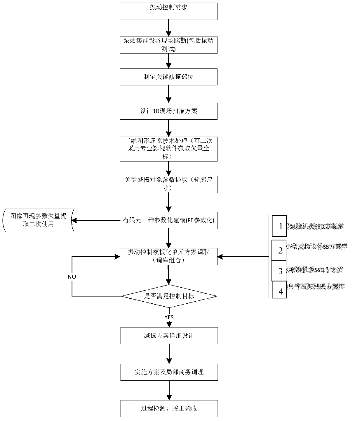
[0031] see figure 1 , a flow chart of a parametric design method for three-dimensional scanning vibration control of existing pump room cluster power equipment, including:

[0032] First put forward the vibration control requirements, and then implement the following steps:

[0033] Step 1. Preliminary data collection: According to the requirements of vibration control technology, conduct field surveys and vibration tests on the pumping station cluster equipment, formulate key vibration reduction parts and obtain data information on key vibration reduction parts;

[0034] Step 2: Design a 3D on-site scanning solution: set up multiple stations, conduct all-round 3D scanning for multiple damping parts, and continuously and automatically collect location information of spatial points and other point source information;

[0035] Step 3: Restoring the three-dimensional graphics: integrating the acquired location information of the spatial points and other point source information ...


PUM


Abstract

The invention provides a three-dimensional scanning vibration control parametric design method for existing pump room cluster power equipment, which comprises the following steps: step 1, preliminarydata acquisition: carrying out on-site survey and vibration test on the pump station cluster equipment, formulating a key vibration reduction part and acquiring data information of the key vibration reduction part; step 2, designing a 3D on-site scanning scheme: setting a plurality of stations, carrying out omnibearing 3D scanning on a plurality of vibration damping parts, and continuously and automatically collecting point source information; step 3, performing restoration processing on the three-dimensional graph: performing data integration on the acquired point source information to generate an actual distribution map of the equipment; step 4, finite element three-dimensional parametric modeling: establishing a finite element model with modifiable design parameters according to the three-dimensional parameters;step 5, performing library adjustment and combination: calling a vibration control modular unit scheme from the library, performing combination debugging until a control target is met, and finally forming a preliminary vibration control design scheme; and step six, detailed design optimization, implementation scheme and local adjustment of the vibration damping scheme arecarried out.

Description

technical field [0001] The invention relates to the field of parametric design methods, in particular to a parametric design method for three-dimensional scanning vibration control of existing pump room cluster power equipment. Background technique [0002] Vibration problems bring many hazards to pump rooms. When the large-scale power equipment in the pump room is in use, it will generate huge and repeatedly changing loads, which cause vertical vibration at the top of the pump room and overall horizontal vibration. The excessive vibration of the structure reduces the dynamic accuracy and performance of the machine, and at the same time makes the workers in it feel uncomfortable and affects their health. For pump rooms with power equipment, structural vibration cannot be completely avoided. Therefore, how to control the impact of vibration within the scope of structural safety, within the scope of not affecting the normal operation of sensitive equipment and operators in th...

Claims


Application Information

Patent Timeline
IPC IPC(8): G06F17/50
Inventor 胡明祎张同亿黄伟兰日清康高轩王胜奎高文坛曹静远徐腾业骆鸿生申超王雨国刘志强周杰刘鑫田放蒋金令
Owner SINOMACH
Learn More