A Method of Reducing the Phase Difference of Electron Beam Radial Oscillation

A technology of radial oscillation and phase difference, applied in transit time electron tubes, parts and circuits of gas discharge lamps, etc., can solve the problems of limitation, difficulty in effectively reducing the radial oscillation of electron beams, lack of understanding, etc. Achieve the effect of improving consistency, improving work efficiency and reliability, and improving beam quality

Active Publication Date: 2021-02-26
NORTHWEST INST OF NUCLEAR TECH
View PDF0 Cites 0 Cited by
  • Summary
  • Abstract
  • Description
  • Claims
  • Application Information

AI Technical Summary

Problems solved by technology

These research foundations can partially provide technical guidance for improving the high-current relativistic electron beam transmission in foil-free diodes, but it is difficult to effectively reduce the radial oscillation of the electron beam under the condition of low guiding magnetic field
[0005] To sum up, there is still insufficient understanding of the root cause of electron beam radial oscillation under the condition of low guiding magnetic field, which limits the proposal of relevant suppression methods, and it is difficult to provide specific and effective information for the optimal design of high-power microwave generation devices with low guiding magnetic field. technical support

Method used


Image

  • A Method of Reducing the Phase Difference of Electron Beam Radial Oscillation
  • A Method of Reducing the Phase Difference of Electron Beam Radial Oscillation
  • A Method of Reducing the Phase Difference of Electron Beam Radial Oscillation

Examples


Embodiment Construction

[0021] The method for reducing the electronic radial oscillation phase difference of the present invention will be described in detail below with reference to the drawings and embodiments.

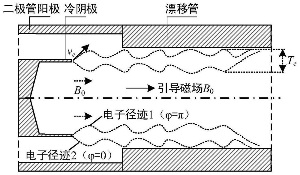
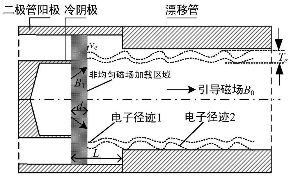
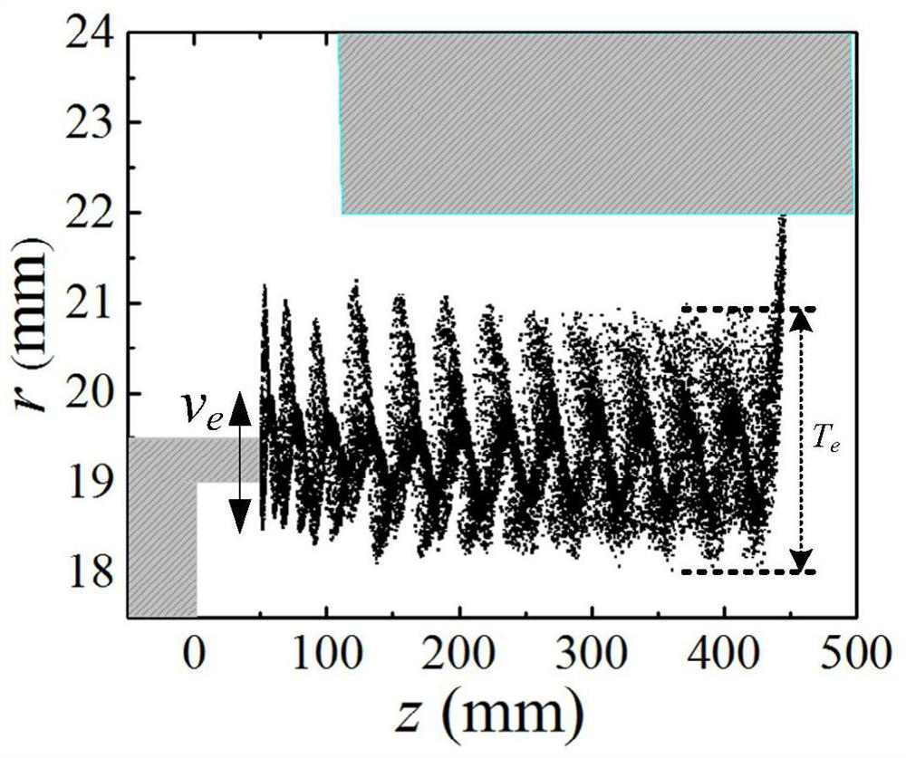
[0022] A schematic diagram of a method for reducing the radial oscillation phase difference of electron beams according to the present invention is as follows: figure 2 shown. In a region of length d near the surface of the cold cathode in a foilless diode, the non-uniform magnetic field B 1 The loading makes the original guided magnetic field B along the axial direction 0 A radial magnetic field component is generated in this region. When an external high-voltage electric pulse drives the cold cathode to explode and emit electrons, under the confinement of the magnetic field, the electrons will accelerate along the magnetic force lines through the diode gap with a length L. Due to the radially outward magnetic field component near the surface of the cold cathode, the initial velocity ...


PUM


Abstract

The invention belongs to the field of high-power microwave technology, and discloses a method for reducing the radial oscillation phase difference of electron beams. The method is based on improving the consistency of the initial phase of electrons emitted by cold cathode explosions, and partly solves the problem of explosive emission under low guiding magnetic field conditions. Radial oscillation problem caused by electron velocity dispersion. The method for reducing the radial oscillation phase difference of the electron beam can be realized by loading a non-uniform magnetic field near the cold cathode explosion emission surface. The loading of the non-uniform magnetic field can adjust the configuration of the guiding magnetic field near the surface of the cold cathode, improve the consistency of the emission direction and movement path of the emitted electrons, and further suppress the radial violent oscillation caused by the velocity dispersion between the electrons. Applying this technology to the development of low-guiding magnetic field high-power microwave generator devices can improve the beam quality of the explosively emitted electron beam and improve the working efficiency and reliability of the high-power microwave generator.

Description

technical field [0001] The invention belongs to the technical field of high-power microwaves, and relates to a method for reducing the radial oscillation phase difference of an electron beam in a foil-free diode. Background technique [0002] The high-power microwave source is an important device for generating high-power microwave radiation by means of high-current relativistic electron beams, and has bright application prospects. At present, the high-current relativistic electron beams required by high-power microwave sources are mainly produced by cold cathodes driven by high-voltage pulses to explode and emit plasma to form plasma. The beam current quality of the electron beam generated by the cold cathode directly determines the working efficiency and reliability of the high-power microwave source, which is an important direction of current high-power microwave technology research. Especially with the development of high-power microwave source technology towards the di...

Claims


Application Information

Patent Timeline
Patent Type & Authority Patents(China)
IPC IPC(8): H01J23/087H01J23/10H01J61/02
Inventor 张广帅孙钧吴平宋志敏范志强曹亦兵
Owner NORTHWEST INST OF NUCLEAR TECH
Why Eureka
Try Eureka