Large-variable-diameter thin-wall pipe composite forming device

A technology for composite forming and thin-walled tubes, which is applied in the field of composite forming devices for large variable-diameter thin-walled tubes, can solve the problems of high scrap rate, low production efficiency, easy cracking and wrinkling, etc., and achieve low cost and high work efficiency , Improve the effect of practicality and economy

Pending Publication Date: 2019-06-14
JIANGXI UNIV OF SCI & TECH
View PDF8 Cites 0 Cited by
  • Summary
  • Abstract
  • Description
  • Claims
  • Application Information

AI Technical Summary

Problems solved by technology

[0006] In order to overcome the shortcomings of thin-walled tubes in the prior art that it is difficult to achieve large deformation ratio forming, easy to crack and wrinkle, serious local thinning, high reject rate and low production efficiency, the technical problem to be solved by the present invention is to provide a A composite forming device for thin-walled tubes with large variable diameters that can realize large deformation ratio forming of thin-walled tubes, uniform thinning of the forming part, good forming effect, less cracking and wrinkling, easy operation, time-saving and labor-saving, and high production efficiency

Method used


Image

  • Large-variable-diameter thin-wall pipe composite forming device
  • Large-variable-diameter thin-wall pipe composite forming device

Examples


Embodiment 1

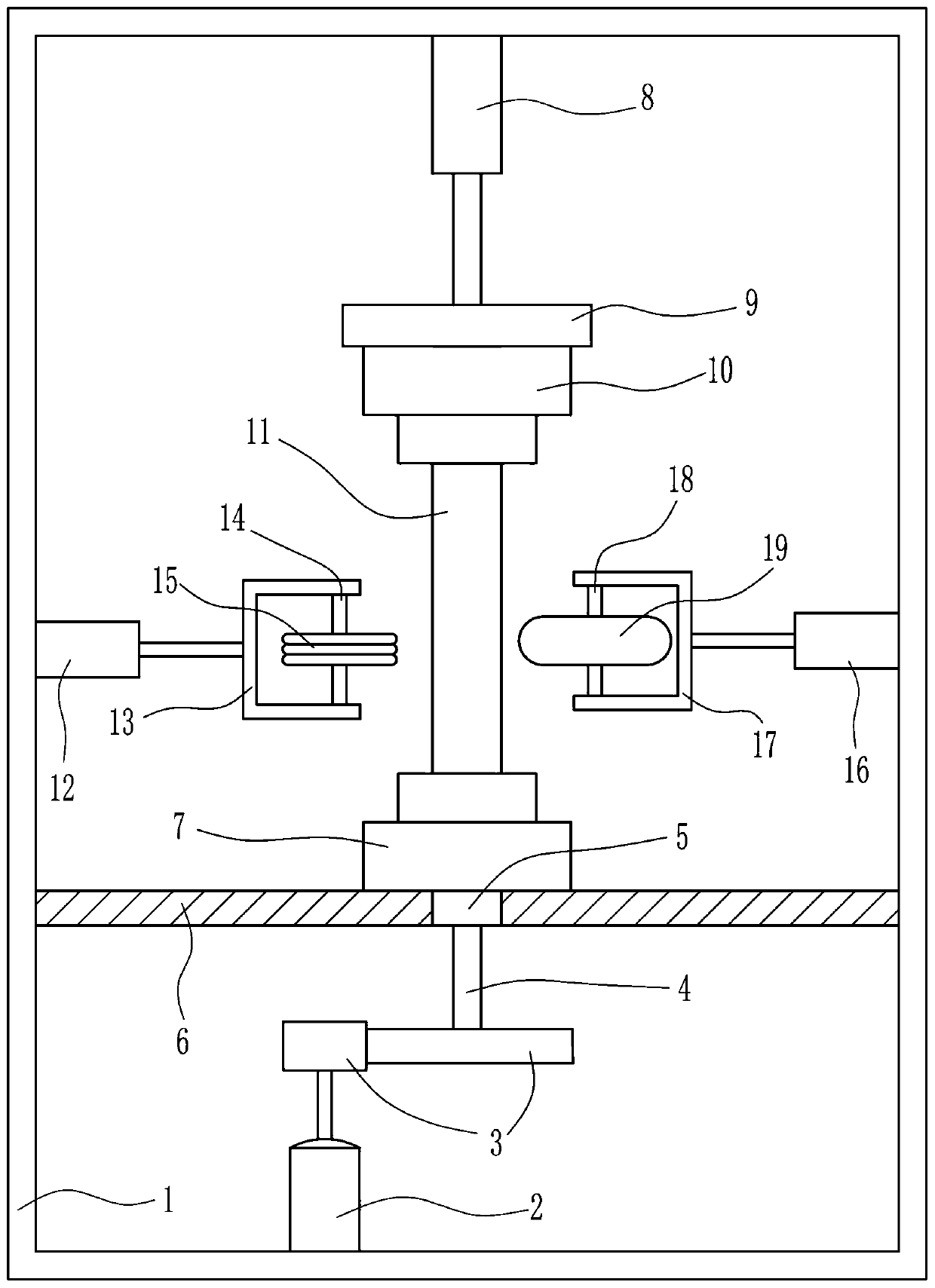
[0028] A compound forming device for large-diameter thin-walled pipes, such as figure 1 As shown, it includes a frame 1, a first motor 2, a transmission device 3, a transmission shaft 4, a first bearing seat 5, a support plate 6, a first clamping device 7, a first push-pull device 8, a connecting plate 9, a first Two clamping devices 10, the second push-pull device 12, the first connecting frame 13, the first rotating shaft 14, the preforming roller 15, the third pushing-pull device 16, the second connecting frame 17, the second rotating shaft 18 and the shaping roller 19, machine The bottom of the frame 1 is fixedly installed with a first motor 2, the output end of the first motor 2 is connected with a transmission device 3, the output end of the transmission device 3 is connected with a transmission shaft 4, and the other end of the transmission shaft 4 is fixedly connected with a first clamping device 7, the transmission The first bearing seat 5 is installed on the shaft 4,...

Embodiment 2

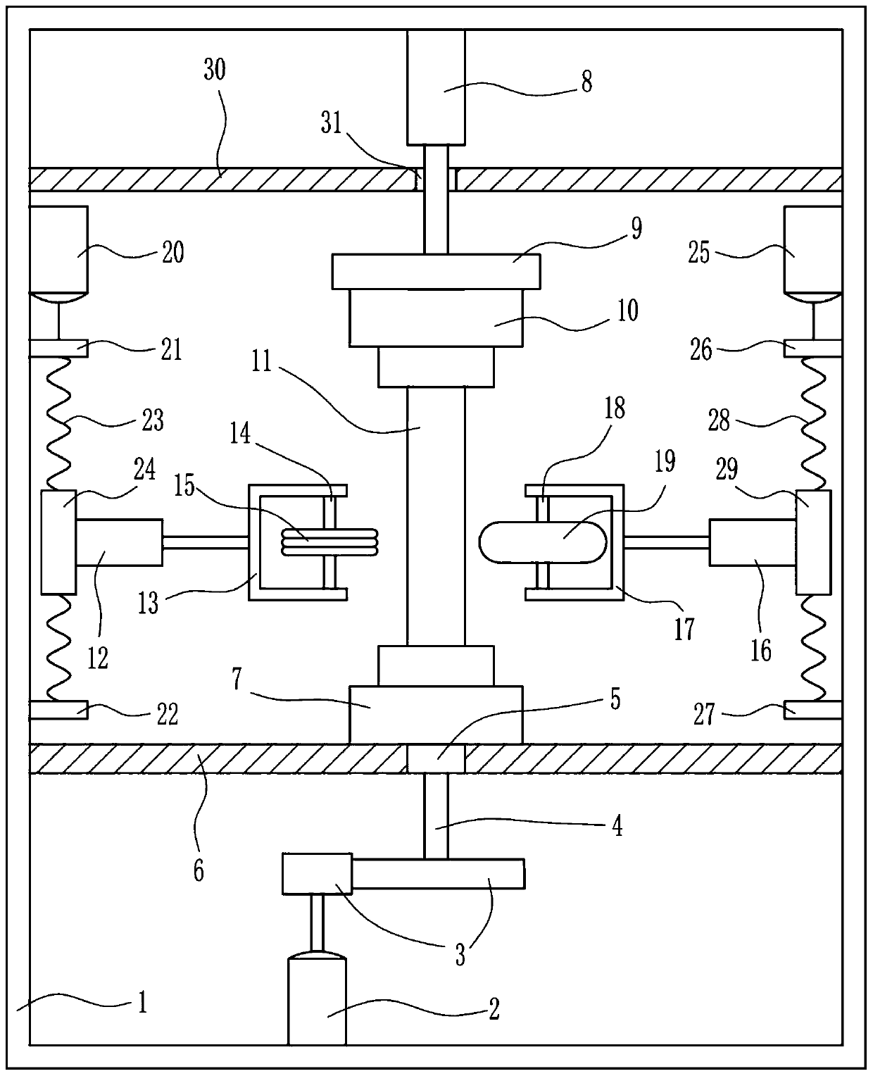
[0031] A compound forming device for large-diameter thin-walled pipes, such as Figure 1-Figure 2 As shown, it includes a frame 1, a first motor 2, a transmission device 3, a transmission shaft 4, a first bearing seat 5, a support plate 6, a first clamping device 7, a first push-pull device 8, a connecting plate 9, a first Two clamping devices 10, the second push-pull device 12, the first connecting frame 13, the first rotating shaft 14, the preforming roller 15, the third pushing-pull device 16, the second connecting frame 17, the second rotating shaft 18 and the shaping roller 19, machine The bottom of the frame 1 is fixedly installed with a first motor 2, the output end of the first motor 2 is connected with a transmission device 3, the output end of the transmission device 3 is connected with a transmission shaft 4, and the other end of the transmission shaft 4 is fixedly connected with a first clamping device 7, the transmission The first bearing seat 5 is installed on th...


PUM


Abstract

The invention relates to a large-variable-diameter thin-wall pipe composite forming device. According to the technical problem to be solved, the large-variable-diameter thin-wall pipe composite forming device can achieve large-variable-ratio formation, and is high in production efficiency. The large-variable-diameter thin-wall pipe composite forming device comprises a rack, a first motor, a transmission device, a transmission shaft, a first clamping device, a first push-pull device, a connecting disc and a second clamping device. The first motor is fixedly installed on the bottom of the rack.The output end of the first motor is connected with the transmission device. The output end of the transmission device is connected with the transmission shaft. The other end of the transmission shaftis fixedly connected with the first clamping device. The first push-pull device is fixedly installed on the top of the rack. The output end of the first push-pull device is connected with the connecting disc. The connecting disc is fixedly connected with the second clamping device. The large-variable-diameter thin-wall pipe composite forming device achieves the effects that thin-wall pipe large-deformation-ratio deformation is convenient and the production efficiency is high. By means of reasonable device layout, the device is simple in structure, and easy and efficient to operate.

Description

technical field [0001] The invention relates to a forming device, in particular to a compound forming device for a thin-walled pipe with large variable diameter. Background technique [0002] The manufacture and application of pipes occupy an important position in the manufacturing industry. Compared with solid steel such as round steel, steel pipes are lighter in weight when they have the same flexural and torsional strength, and are widely used in the manufacture of structural parts and mechanical parts, such as oil drill pipes, automobile drive shafts and bicycle frames. Steel pipe is also an indispensable material for various conventional weapons, and steel pipes are required for the manufacture of gun barrels and barrels. Lightweight structure is one of the main means for vehicles, airplanes and rockets to save fuel, reduce pollutant emissions and improve maneuverability. As "energy saving and environmental protection" is getting more and more attention, lightweight i...

Claims


Application Information

Patent Timeline
Patent Type & Authority Applications(China)
IPC IPC(8): B21D35/00
Inventor 张池黄丽容陈宇航罗开臣
Owner JIANGXI UNIV OF SCI & TECH
Why Eureka
Try Eureka