
A press that facilitates the replacement of pressure supply elements

A component and pressure technology, which is applied in the field of presses for easy replacement of pressure supply components, can solve the problems of high work efficiency, low price of hydraulic jacks, low work efficiency, etc., and achieve the goal of reducing labor intensity, saving labor costs and reducing maintenance time Effect

Active Publication Date: 2022-04-12
济南宏光数控机械有限公司
View PDF0 Cites 0 Cited by
  • Summary
  • Abstract
  • Description
  • Claims
  • Application Information

AI Technical Summary

Problems solved by technology

Presses using electric cylinders have low labor intensity and high work efficiency, but the thrust they can provide is generally below 35 tons, and the price will increase significantly if it exceeds 35 tons, but the thrust of 35 tons cannot meet the maintenance needs of some large extruders ;The press machine using the hydraulic jack has high labor intensity and low work efficiency, but the price of the hydraulic jack is low, and it can be used in the state of power failure
An effective solution is to use the electric cylinder as the pressure supply element of the press when the required pressure is low. When the required pressure is higher than the maximum thrust of the electric cylinder or when the power is off, use a hydraulic jack to replace the electric cylinder for use, but The pressure supply element of the existing press is to fix its base on its support structure, and the shape and size of the base of different pressure supply elements are not the same, and the positions of the installation holes are also different, so there is no way to preset the installation holes. It is very difficult to replace the pressure supply element, and the higher position of the pressure supply element is also difficult to replace

Method used


Image

  • A press that facilitates the replacement of pressure supply elements
  • A press that facilitates the replacement of pressure supply elements
  • A press that facilitates the replacement of pressure supply elements

Examples


Embodiment Construction

[0038] In order to make the purpose, technical solutions and advantages of the embodiments of the present invention clearer, the technical solutions in the embodiments of the present invention will be clearly and completely described below in conjunction with the accompanying drawings in the embodiments of the present invention. Obviously, the described embodiments It is some embodiments of the present invention, but not all of them. Based on the implementation manners in the present invention, all other implementation manners obtained by persons of ordinary skill in the art without creative efforts fall within the protection scope of the present invention. Accordingly, the following detailed description of the embodiments of the invention provided in the accompanying drawings is not intended to limit the scope of the claimed invention, but merely represents selected embodiments of the invention. Based on the implementation manners in the present invention, all other implement...


PUM


Abstract

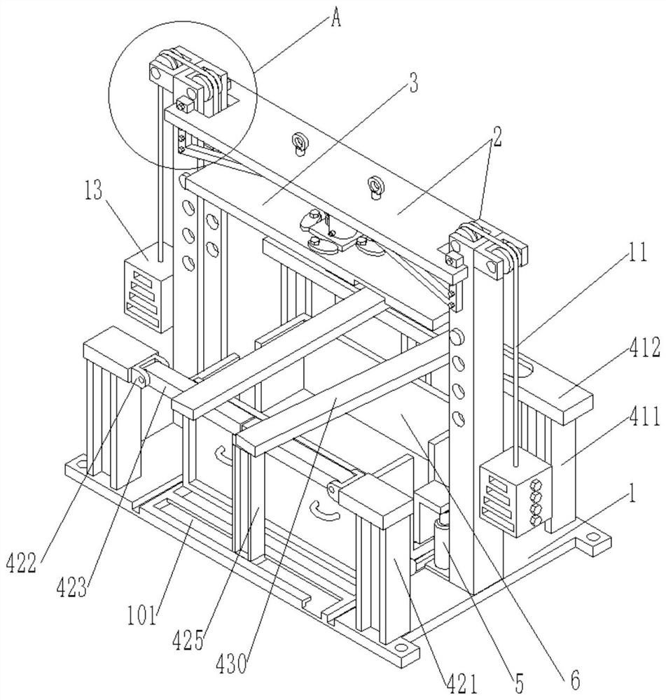
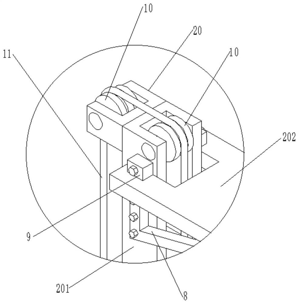
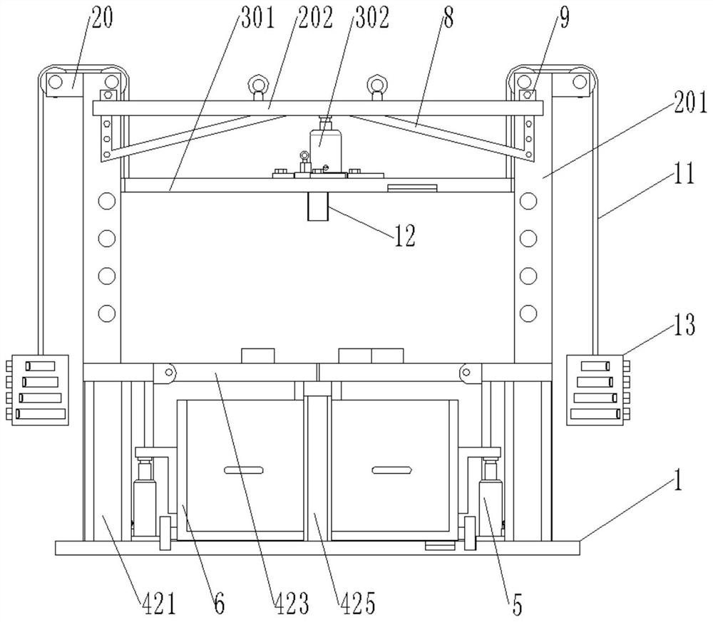
The invention discloses a press machine for easy replacement of pressure supply components, which comprises a base, a fixed frame, a pressure device and a frame holder. The top plate is composed of a pressure device, which includes a pressure plate and a pressure supply element, and an elliptical column-shaped fixed block for fixing the base of the pressure supply element is arranged on the upper end surface of the pressure plate; The supply element is fixedly installed on the pressure plate, just place the pressure supply element in the middle of the upper surface of the pressure plate, and then install the four fixing blocks on the four threaded through holes on the outside of the bottom of the pressure supply element through bolts, and turn the fixing block to fix The block is in close contact with the bottom of the pressure supply element, and then the bottom of the pressure supply element can be fixed by tightening the bolts for installing the fixing block, so that different pressure supply elements can be easily replaced.

Description

technical field [0001] The invention relates to the field of press machines, in particular to a press machine for easy replacement of pressure supply elements. Background technique [0002] Screw extruder is a common plastic extrusion machine, which has the advantages of high production efficiency, strong adaptability and wide application. The tail end of the screw of the screw extruder is usually installed at one end of the main shaft of the extruder gearbox. When the screw is extruding, it will bear the reaction force of the material to be extruded, and will be affected by both axial force and radial force. Therefore, the main shaft of the installation screw will also be affected by axial force and radial force at the same time, so the end of the main shaft of the installation screw close to the installation screw usually uses a thrust roller bearing. This thrust roller bearing is the extruder gearbox. The most vulnerable parts in the thrust roller bearing, the damage is ...

Claims


Application Information

Patent Timeline
Patent Type & Authority Patents(China)
IPC IPC(8): B23P19/027
Inventor 贾棋棋李雨杭
Owner 济南宏光数控机械有限公司
Learn More