
Composite material structure and production method thereof

A technology of composite materials and production methods, applied in the direction of chemical instruments and methods, synthetic resin layered products, layered products, etc., can solve the problems of restricted steel use, rust, safety performance decline, etc., to achieve enhanced tensile strength , high yield resistance, and the effect of saving steel

Pending Publication Date: 2019-06-14
海添琪
View PDF6 Cites 2 Cited by
  • Summary
  • Abstract
  • Description
  • Claims
  • Application Information

AI Technical Summary

Problems solved by technology

[0002] In the prior art, steel is often used in the fields of aerospace, aviation, automobile, electronics, machinery, chemical industry, light textile and other civil industries, sports equipment and leisure products, but it is inconvenient to use steel to process curved surfaces
If there is a welding process, the intersecting lines of the surface welding nodes are complicated, which brings great inconvenience to the manufacturing process
Moreover, steel will rust when in contact with air, it is very difficult to remove rust, and the corrosion resistance is poor.
In today's extreme pursuit of lightweight equipment, if lightweight steel is used and the tube wall is thinned by pumping tube technology, it will lead to a decrease in safety performance and limit the use of steel, so it is rarely used in competition-level frames. see steel frame

Method used


Image

  • Composite material structure and production method thereof
  • Composite material structure and production method thereof
  • Composite material structure and production method thereof

Examples


Embodiment Construction

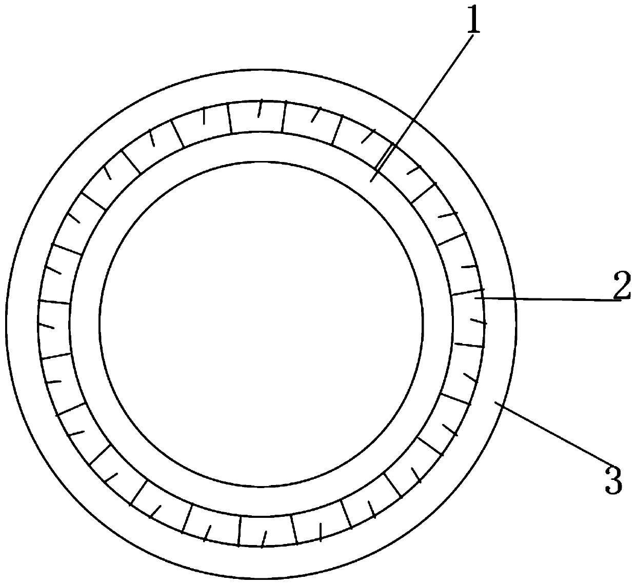
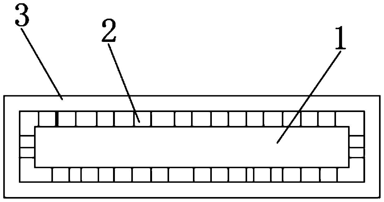
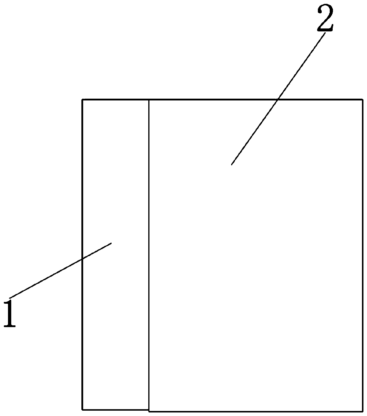
[0082] Such as Figure 1 to Figure 4 As shown, this embodiment provides a composite material structure, the surface of the matrix 1 is coated with a carbon fiber material 2 and a prepreg 3, and the prepreg 3 is impregnated into the carbon fiber material 2 to form a composite layer.

[0083] In this embodiment, the surface of the matrix is ​​covered with carbon fiber material and prepreg, and the technical means of impregnating the prepreg into the carbon fiber material to form a composite layer is adopted. Therefore, the yield resistance is high, the strength is high, and the strength is enhanced. Tensile strength, becoming lighter and more corrosion-resistant, can greatly save steel during processing, making this material not only widely used in aerospace, aviation, automobiles, electronics, machinery, chemicals, textiles and other civil industries , sports equipment and leisure products and other fields, it can also be used in military fields such as aircraft manufacturing, ...


PUM

PropertyMeasurementUnit
Tensile strengthaaaaaaaaaa
Yield strengthaaaaaaaaaa

Abstract

The invention discloses a composite material structure and a production method thereof. The composite material structure comprises a base body, wherein a carbon fiber material and a prereg material cover the surface of the base body; the prereg material is immersed into the carbon fiber material to form a composite layer. The production method comprises the following steps of 1, preparing the basebody, the carbon fiber material and the prereg material; 2, coating the base body with the carbon fiber material; 3, brushing the prereg material onto the base body coated with the carbon fiber material so that the prereg material is immersed into the carbon fiber material to form a composite layer; performing drying. The composite material structure has the advantages that the yield resistance is high; the intensity is high; the tensile intensity is enhanced; the weight becomes light; meanwhile, the anti-corrosion performance is realized; in the processing and manufacturing process, the steel materials can be greatly saved, so that the material can be widely applied to various fields.

Description

technical field [0001] The invention relates to a material and a production method thereof, in particular to a composite material structure and a production method thereof. Background technique [0002] In the prior art, steel is often used in the fields of aerospace, aviation, automobile, electronics, machinery, chemical industry, light textile and other civil industries, sports equipment and leisure products, but it is inconvenient to use steel to process curved surfaces. If there is a welding process, the intersecting lines of the surface welding nodes are complicated, which brings great inconvenience to the manufacturing process. Moreover, the steel will rust when in contact with the air, and it is very difficult to remove the rust, and the corrosion resistance is poor. In today's extreme pursuit of lightweight equipment, if lightweight steel is used and the tube wall is thinned by pumping tube technology, it will lead to a decrease in safety performance and limit the u...

Claims


Application Information

Patent Timeline
IPC IPC(8): B32B1/08B32B9/00B32B9/04B32B15/14B32B15/20B32B27/06B32B27/12B32B27/40B32B33/00
Inventor 海添琪
Owner 海添琪
Learn More