Two-translation one-rotation large-stroke uncoupled parallel piezoelectric micro-motion platform

A technology of micro-movement platform and large stroke, which is applied in the field of micro-displacement mechanism, two translations and one rotation and large stroke without coupling in parallel piezoelectric micro-movement platform, which can solve the problems of complex parallel structure, small work surface and low natural frequency. , to achieve the effect of simple and compact structure, large working table, and enlarged displacement stroke

Active Publication Date: 2019-06-14
NINGBO UNIV
View PDF9 Cites 0 Cited by
  • Summary
  • Abstract
  • Description
  • Claims
  • Application Information

AI Technical Summary

Problems solved by technology

The superposition type is to firstly manufacture a single-degree-of-freedom piezoelectric micro-motion platform that can output micro-displacement along the x, y, and z directions, and then stack the three platforms in layers in the height direction. This kind of platform design is easy. There is no coupling in motion (that is, when the platform moves in a certain direction, there will be no parasitic displacement in the other direction), and the installation and pre-tightening of the piezoelectric actuator are convenient, but the volume is large, the structure is not compact, the natural frequency is low, and each direction of motion The performance parameters need to be designed separately
The serial type is to first make a moving platform (intermediate moving platform) that can produce movement in another direction on the moving platform (outer moving platform) that produces movement in one direction, and then make a moving platform that can produce movement in the last direction in the middle moving platform. The moving platform (inner moving platform) has a compact structure, and each moving platform has no coupling in motion, but the effective table is small, and the piezoelectric actuators used to drive the intermediate moving platform and the inner moving platform are installed and preloaded Difficult, the performance parameters of each direction of motion also need to be designed separately
The parallel type uses the same moving platform to realize the movement in all directions. It is convenient to install and pre-tighten the piezoelectric actuator. The performance parameters of each movement direction can be designed at the same time. The structure is complex and not compact, the working surface is small, the displacement stroke is small, there is displacement coupling, and the natural frequency is low

Method used


Image

  • Two-translation one-rotation large-stroke uncoupled parallel piezoelectric micro-motion platform
  • Two-translation one-rotation large-stroke uncoupled parallel piezoelectric micro-motion platform
  • Two-translation one-rotation large-stroke uncoupled parallel piezoelectric micro-motion platform

Examples


Embodiment 1

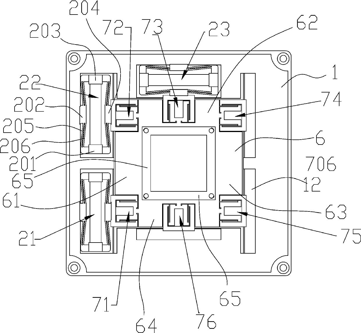
[0047] The first conduction part 71 to the sixth conduction part 76 of the first embodiment have two second receiving grooves 701, two rigid parts 703, and the first convex part 704, the second convex part 702 and the second convex part 702. The number of a flexible thin plate 705 is 2 and it is arranged between two adjacent rigid parts 703, and the two adjacent rigid parts 703 are integrally formed at one end located in the third receiving groove 12, Between the adjacent rigid parts 703, there is a hollow groove for screwing the screws into the fourth rigid block 204, such as Figure 9 shown.

Embodiment 2

[0048] The difference between Embodiment 2 and Embodiment 1 is that the fourth conducting portion 74 to the sixth conducting portion 76 of Embodiment 2 do not have hollow grooves, such as Figure 10 shown.

Embodiment 3

[0049] The difference between Embodiment 3 and Embodiment 1 is that the number of second receiving grooves 701 of the fourth conduction part 74 to the sixth conduction part 76 of Embodiment 3 is one, the number of rigid parts 703 is one, and the first The number of the convex part 704, the second convex part 702 and the first flexible thin plate 705 are respectively 2 and are respectively arranged on both sides of the rigid part 703, such as Figure 11 shown.

[0050] The first rigid block 201, the second rigid block 202, the third rigid block 203, the fourth rigid block 204, the third flexible thin plate 205 and the fourth flexible thin plate 206 are composed of a bridge-type amplifying mechanism 2 integrally formed structure; fixed platform The body 11 , the second flexible thin plate 706 , the rigid portion 703 , the first convex portion 704 , the first flexible thin plate 705 , the second convex portion 702 and the moving table body 6 are integrally formed. Let the z-axis...


PUM


Abstract

The invention discloses a two-translation one-rotation large-stroke uncoupled parallel piezoelectric micro-motion platform which comprises a movable table board used for bearing an object, a fixed table body is arranged below the movable table board in a gap mode, a first containing groove is formed in the middle of the fixed table body, and a movable table body screwed and fixed to the movable table board is arranged in the gap of the first containing groove. The movable table body is further provided with a first conduction part, a second conduction part and a third conduction part. A thirdaccommodating groove for accommodating the second flexible thin plate at an interval is formed in the edge, located in the first accommodating groove, of the fixed table body. A first driving unit, asecond driving unit, and a third driving unit, each of which has a respective rigid portion of the first, second, and third conduction portions. And the first driving unit, the second driving unit andthe third driving unit are driven to realize two translational motions and one rotation of the movable platform body and the movable platform surface in the horizontal plane. The platform has the advantages of being simple and compact in overall structure, large in working table top, large in displacement stroke, free of parasitic displacement, high in inherent frequency and easy to integrate a displacement type sensor.

Description

technical field [0001] The invention belongs to the field of nano-positioning technology, and relates to a micro-displacement mechanism in a nano-positioning system, in particular to a two-translation and one-rotation large-stroke non-coupling parallel piezoelectric micro-motion platform. Background technique [0002] The piezoelectric micro-motion platform is a micro-displacement mechanism that transmits displacement and force by driving a flexible mechanism that can produce elastic deformation through a piezoelectric actuator. Because it has no hinges and bearings, it does not require assembly, there is no transmission gap, and no friction and wear; because it is driven by a piezoelectric actuator, its displacement resolution can reach nanometers, and its response time can reach milliseconds. Large, small size, strong carrying capacity. Therefore, it is widely used in technical fields that require micro / nano positioning, such as precision processing and testing, optical f...

Claims


Application Information

Patent Timeline
Patent Type & Authority Applications(China)
IPC IPC(8): B81C99/00
Inventor 崔玉国张圣贤娄军强马剑强周鹏飞惠相君
Owner NINGBO UNIV
Why Eureka
Try Eureka