Optimization structure of combined foam flow field for solid oxide electrolysis tank

A solid oxide, optimized structure technology, applied in the direction of electrolysis components, electrolysis process, electrodes, etc., can solve the problems of large transmission resistance and uneven distribution.

Inactive Publication Date: 2019-06-14
TIANJIN UNIV
View PDF10 Cites 0 Cited by
  • Summary
  • Abstract
  • Description
  • Claims
  • Application Information

AI Technical Summary

Problems solved by technology

In this structure, the transmission resistance of the reactive gas from the flow channel to the porous medium under the ridge is too large, which makes the distribution of the reactive gas in the porous medium uneven

Method used


Image

  • Optimization structure of combined foam flow field for solid oxide electrolysis tank
  • Optimization structure of combined foam flow field for solid oxide electrolysis tank
  • Optimization structure of combined foam flow field for solid oxide electrolysis tank

Examples


Embodiment Construction

[0019] The principle and structure of the present invention will be described in detail below in conjunction with the accompanying drawings and specific examples. The present implementation that needs to be explained is descriptive rather than restrictive, and is not intended to limit the protection scope of the present invention.

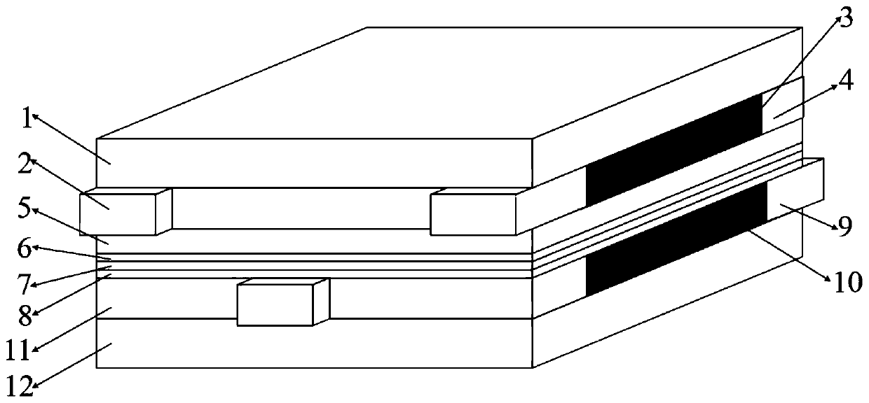
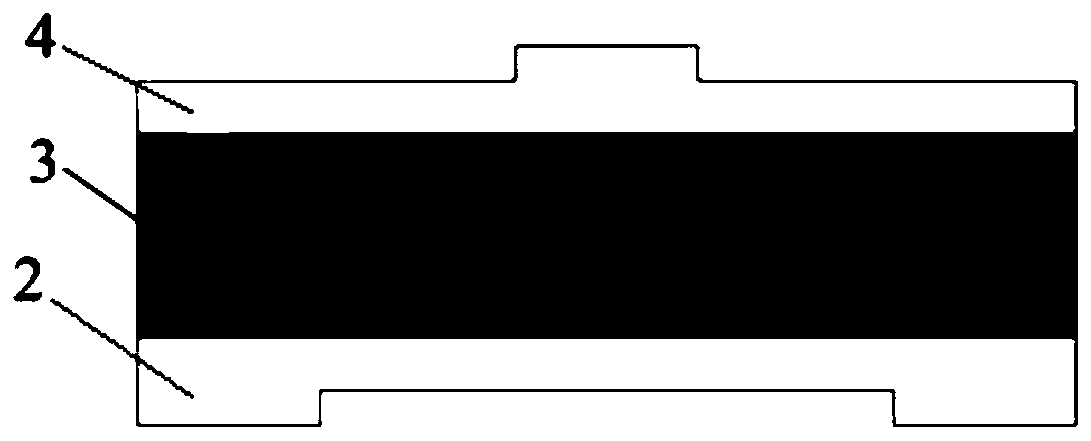
[0020] The optimized structure of the solid oxide electrolytic cell combined foam flow field (such as figure 1 ), which is characterized in that the cathode inlet cavity distribution area 2, the cathode metal foam 3 and the cathode outlet gathering area 4 are sequentially connected horizontally to form a cathode flow field (such as figure 2 ), and the flow field is placed between the cathode bipolar plate 1 and the cathode gas diffusion layer 5. The anode inlet cavity distribution area 9 , the anode metal foam 10 and the anode outlet accumulation area 11 are sequentially connected horizontally to form an anode flow field, and the flow field is pla...


PUM

PropertyMeasurementUnit
thicknessaaaaaaaaaa
thicknessaaaaaaaaaa
thicknessaaaaaaaaaa

Abstract

The invention discloses an optimization structure of a combined foam flow field for a solid oxide electrolysis tank. The structure is concretely characterized in that a cathode inlet cavity distribution zone, a cathode metal foam and a cathode outlet agglomeration zone are sequentially connected to form a cathode flow field, and the flow field is placed between a cathode bipolar plate and a cathode gas diffusion layer. An anode inlet cavity distribution, an anode metal foam and an anode outlet agglomeration zone are horizontally connected to form an anode flow field, and the flow field is placed between an anode bipolar plate and an anode catalysis layer. The connection order of the cathode inlet cavity distribution zone, the cathode metal foam and the cathode outlet agglomeration zone isopposite to the connection order of the corresponding zones of the anode, and the directions of two gas flow paths intersect with each other. The metal foams have good electrical and thermal conductivity, have a large porosity, and can promote the transmission of gases from the flow fields to the diffusion layer and the catalysis layer, so the concentration of reactants in the cathode catalysis layer is increased, the concentration of an anode product is reduced, and the matter distribution uniformity is improved.

Description

technical field [0001] The invention belongs to the field of electrochemistry and electrolytic cells, and in particular relates to a novel flow field structure of a solid oxide electrolytic cell. Background technique [0002] Due to the increase in energy demand and the massive emission of carbon dioxide, renewable energy technology and energy saving and emission reduction technology have become the focus of research at home and abroad. CO in the environment 2 The increase in the content makes the CO 2 Storage and utilization become CO reduction 2 effective way of content. The solid oxide co-electrolytic cell can store the electrical energy generated by renewable energy power generation in the form of chemical energy, and at the same time convert CO 2 Conversion to useful fuel (syngas) to achieve CO 2 efficient storage and utilization. Therefore, solid oxide electrolytic cells are considered as CO 2 Neutral recycling and utilization is a very promising approach. [0...

Claims


Application Information

Patent Timeline
Patent Type & Authority Applications(China)
IPC IPC(8): C25B1/00C25B1/06C25B9/06C25B11/03C25B11/06C25B9/17
CPCY02E60/36
Inventor 尹燕杜迎梦焦魁杜青
Owner TIANJIN UNIV
Why Eureka
Try Eureka