Fan control system and method and server

A fan control and controller technology, applied in pump control, machine/engine, non-variable-capacity pump, etc., can solve the problems of waste of resources, occupy more space, and high cost, reduce complexity, improve stability, The effect of preventing shutdown

Active Publication Date: 2019-06-14
INSPUR BUSINESS MACHINE CO LTD
View PDF5 Cites 11 Cited by
  • Summary
  • Abstract
  • Description
  • Claims
  • Application Information

AI Technical Summary

Problems solved by technology

[0004] On the one hand, because the number of fan terminals may be large, for example, there may be 16 fan terminals on the fan control board of some servers, and each fan terminal needs a corresponding fan control signal, resulting in the number of fan control signals that need to be transmitted There are many, so that when the fan control board is connected to the BMC, it is necessary to select a connector with a large number of pins. This type of connector is large in size and high in cost, and will take up more space. feet, resulting in a waste of resources
[0005] On the other hand, when the BMC is abnormal and stops working, because the BMC cannot continue to control the fan rotation, the fan stop may cause the server to stop due to overheating, which affects the stability of the server system

Method used


Image

  • Fan control system and method and server
  • Fan control system and method and server
  • Fan control system and method and server

Examples


Embodiment 1

[0037] Embodiment 1 of the present application provides a fan control system, which will be described in detail below with reference to the accompanying drawings.

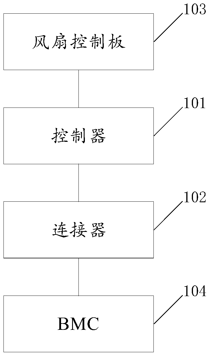
[0038] see figure 1 , which is a structural diagram of a fan control system provided in Embodiment 1 of the present application.

[0039] The fan system is used to control the server fan, wherein the server may have one or more fan terminals, the application does not specifically limit the number of fan terminals, the server also has a fan control board 103, through the fan control board 103 to realize the control of each fan terminal The data is collected and the regulation signal of the fan is sent to each fan terminal. The BMC104 on the server can be used to identify whether the fan terminal is in place, and then determine whether it is necessary to supply power to the fan terminal. It can also be used to monitor the temperature of the server system in real time and control the speed of each fan terminal throug...

Embodiment 2

[0053] Embodiment 2 of the present application also provides another fan control system, which will be described in detail below with reference to the accompanying drawings.

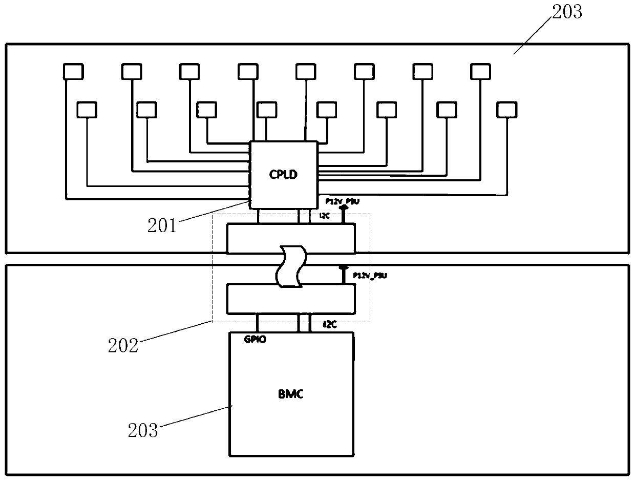
[0054] see figure 2 , which is a structural diagram of another fan control system provided in Embodiment 2 of the present application.

[0055] The system includes: CPLD201 and connector 202 .

[0056] In this embodiment, 16 fan terminals are provided on the fan control board 101 as an example for illustration. It can be understood that other numbers of fan terminals may also be provided on the fan control board.

[0057] Wherein, the system is explained by taking the controller as CPLD (Complex Programmable Logic Device, complex programmable logic device) as an example. It can be understood that the controller can also be single-chip microcomputer, FPGA (Field-programmable Gate Array, field programmable Gate Array) and a combination of one or more of DSP (Digital Signal Processor, digital signal proc...

Embodiment 3

[0068] Embodiment 3 of the present application also provides a fan control method, which can be applied to the fan control system provided in the present application, and will be described in detail below with reference to the accompanying drawings.

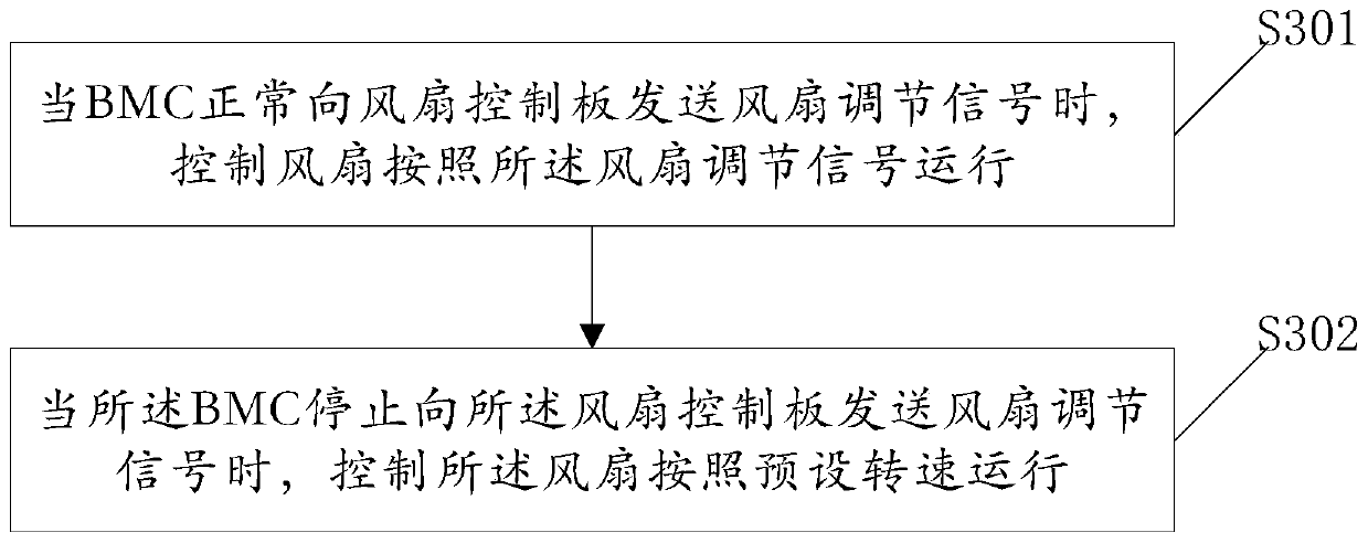
[0069] see image 3 , which is a flowchart of a fan control method provided in Embodiment 3 of the present application.

[0070] The method includes the following steps:

[0071] S301: When the BMC normally sends a fan adjustment signal to the fan control board, control the fan to run according to the fan adjustment signal.

[0072] When the controller judges that the BMC is working normally, it converts the fan in-position signal received in parallel into serial data and sends it to the BMC. At the same time, the BMC monitors the temperature of each module of the server in real time. The controller receives the fan adjustment signal sent by the BMC in serial, and then converts the fan adjustment signal into a parallel signal a...


PUM


Abstract

The invention provides a fan control system, and further provides a fan control method and a server. The fan control system comprises a controller and a connector. A first end of the controller is connected with a fan control panel, and the other end of the controller is connected with a baseboard management controller (BMC) through the connector. The controller is used for controlling a fan to operate according to a preset rotating speed when the BMC stops sending fan adjusting signals to the fan control panel. The connector is used for realizing information communication between the controller and the BMC. By means of the fan control system, the number of interfaces which are used when the fan control panel and the BMC are connected can be reduced, so that the connector with the small size and the low cost can be selected, the complexity of circuit design is reduced, the fan can be continuously controlled to rotate when the BMC fails, the server is prevented from being turned off dueto overheating, and the stability of a server system is improved.

Description

technical field [0001] The present invention relates to the technical field of power electronics, in particular to a fan control system, method and server. Background technique [0002] With the continuous development of networking, the application of data centers in enterprises is becoming more and more extensive. The installation density of server cabinets as the constituent units of data centers is increasing. At the same time, due to the improvement of server performance, the number of components and power consumption of server cabinets are increasing rapidly As a result, the heat dissipation resistance of the server cabinet is large, the heat flux density is high, and the heat dissipation performance is poor, which seriously affects the performance of the cabinet and even leads to the occurrence of thermal failure. [0003] In view of this phenomenon, the current server cabinets are often installed with multiple fans for heat dissipation. At the same time, in order to b...

Claims


Application Information

Patent Timeline
Patent Type & Authority Applications(China)
IPC IPC(8): F04D27/00
Inventor 张昌辉张志安
Owner INSPUR BUSINESS MACHINE CO LTD
Why Eureka
Try Eureka