
Distance measuring device and distance measuring method used for magnetizing exciter

The technology of a distance measuring device and a distance measuring method, which is applied in the field of nuclear power, can solve problems such as damaged probes and poor measurement accuracy, and achieve the effects of improving measurement accuracy, easy operation, and saving time

Active Publication Date: 2019-06-14
CHINA GENERAL NUCLEAR POWER OPERATION +2
View PDF5 Cites 2 Cited by
  • Summary
  • Abstract
  • Description
  • Claims
  • Application Information

AI Technical Summary

Problems solved by technology

This requires starting and stopping the car at least 117 times, and then considering the incorrect fastening components and multiple starts of the car, the number of times for each measurement may reach hundreds of times, which takes several days
In the process of using the feeler gauge for many times, in case the person who starts the crank and the person who measures the distance cooperates incorrectly, the crank starts with the feeler gauge inserted, which will lead to problems such as damage to the probe.
[0004] And because the diode probe and the fastening component are not on the same plane in the axial direction, when measuring, it is necessary to use a feeler gauge to press the fastening component, and the other end touches the bottom surface of the probe for measurement, and the measurement accuracy is poor

Method used


Image

  • Distance measuring device and distance measuring method used for magnetizing exciter
  • Distance measuring device and distance measuring method used for magnetizing exciter
  • Distance measuring device and distance measuring method used for magnetizing exciter

Examples


Embodiment Construction

[0039] In order to have a clearer understanding of the technical features, purposes and effects of the present invention, the specific implementation manners of the present invention will now be described in detail with reference to the accompanying drawings.

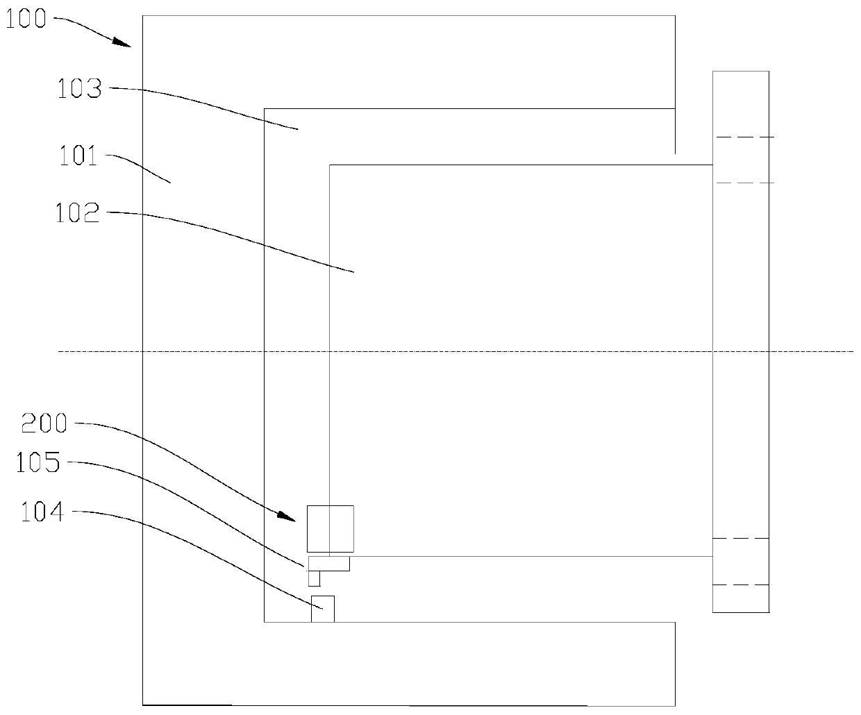
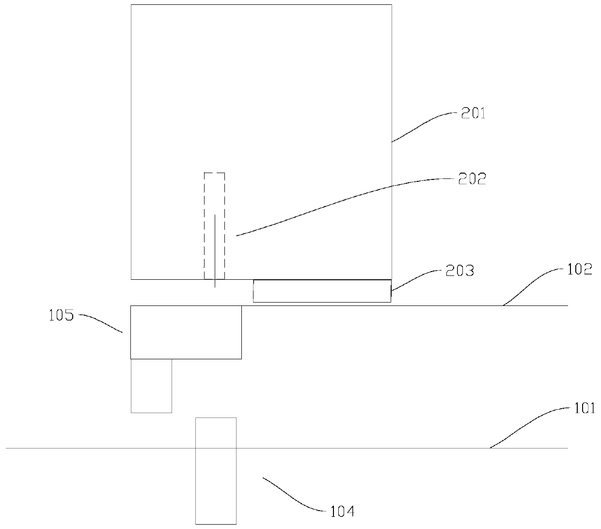
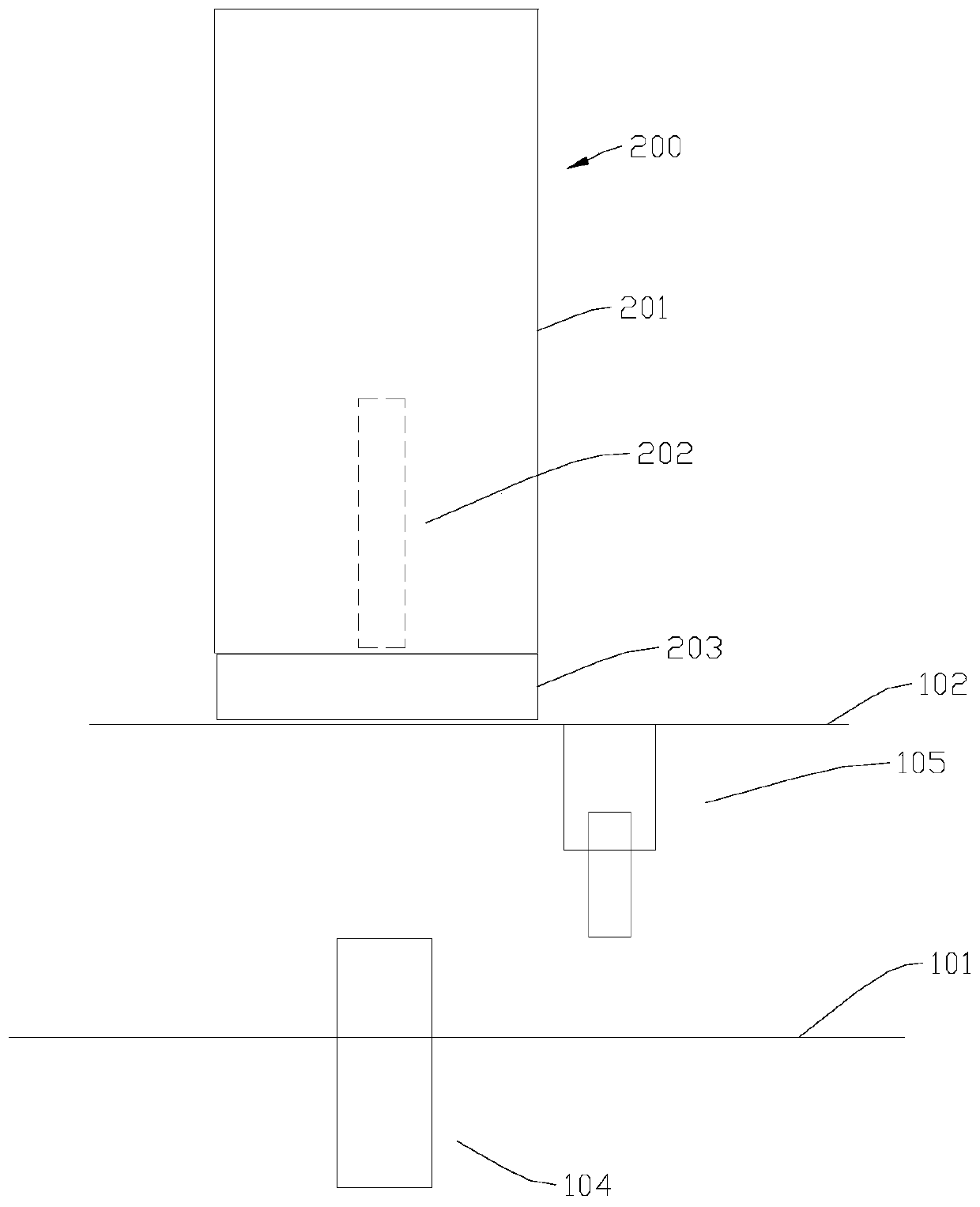
[0040] Figure 1 to Figure 7 A preferred embodiment of the distance measuring device for an exciter according to the present invention is shown.

[0041]The distance measuring device can be used for the maintenance of the exciter 100, the exciter 100 includes an armature 101, a stator 102, and an air gap, the armature 101 is arranged on the periphery of the stator 102, and the air gap 103 is arranged on the Between the stator 102 and the armature 101. The stator 102 is provided with at least one diode probe 105 on the side wall opposite to the armature 101; the armature 101 is provided with a plurality of fastening components 104; the fastening components 104 can be used to fix the fuse on Armature 101 on. The plural...


PUM


Abstract

The invention relates to a distance measuring device and a distance measuring method used for a magnetizing exciter. The distance measuring device comprises a first distance measuring unit and a second distance measuring unit; the first distance measuring unit is arranged at a stator and comprises a distance measuring probe; the distance measuring probe is arranged oppositely to the inner sidewallof an armature so that the distance between each fastening assembly and the distance measuring probe is measured and a group of first measuring values is obtained when each fastening assembly turns to be opposite to the distance measuring probe; the second distance measuring unit is arranged between any fastening assembly and a diode probe to obtain second measuring values, further an offset of the distance measuring probe and a diode probe is obtained by using a difference between the first measuring values and second measuring values which are corresponding obtained by measuring the same fastening assembly, and distances from end faces where the rest fastening assemblies and the stator are arranged oppositely to the diode probe are obtained by using the difference between the first measuring values corresponding to the rest fastening assemblies and the offset. By adopting the distance measuring device, the distance measuring device has advantages of high efficiency and high security.

Description

technical field [0001] The invention relates to the technical field of nuclear power, more specifically, to a distance measuring device for an exciter and a distance measuring method thereof. Background technique [0002] In the overhaul of nuclear power plants, it is necessary to measure the distance between the rotating diode probe and the fuse fastening assembly, especially the distance between the rotating diode probe and the fuse nut. The current measurement method is to use a manual turning device to turn the fuse fastening assembly at an angle so that the fastening assembly is directly facing the bottom of the diode probe, and then measure the distance with a feeler gauge. Because the fuse fastening component is linked with the generator rotor, the weight of the entire shafting is several hundred tons. After the manual crank is stopped, it will continue to rotate at a random angle due to inertia. It often happens that the fastening component does not correspond to the...

Claims


Application Information

Patent Timeline
Patent Type & Authority Applications(China)
IPC IPC(8): G01B11/14G01B5/14
Inventor 王建涛
Owner CHINA GENERAL NUCLEAR POWER OPERATION
Learn More