Torsional shear force measurement device for adhesion strength between material surfaces and icing layer

A technology of adhesion strength and measuring device, which is applied in the direction of measuring device, using stable shear force to test material strength, analyzing materials, etc., can solve the problems of dangerous use, high speed of measuring device, difficult operation, etc., to achieve The effect of simple and convenient operation, low manufacturing cost and high measurement accuracy

Active Publication Date: 2019-06-14
NORTHEAST AGRICULTURAL UNIVERSITY
View PDF32 Cites 10 Cited by
  • Summary
  • Abstract
  • Description
  • Claims
  • Application Information

AI Technical Summary

Problems solved by technology

Among them, the measuring device used in the static measurement method uses tensile force to measure the adhesion strength and shear force between the surface of the material and the ice layer. When testing, it is necessary to control the direction of the pulling force to be parallel to the shear plane, which is difficult to operate and requires the ice layer If the thickness is large, otherwise there will be measurement errors; the dynamic measurement method is to use the rotating centrifugal force to separate the ice layer from the surface of the material, so as to realize the measurement of the adhesion between the two, but the centrifugal ice adhesion force used in it is The rotating speed of the measuring device is high, the dynamic balance of the rotating device needs to be met during the measurement, and the high-speed photography device is also required. The structure is complex, the equipment cost is high, the experiment is difficult, and there are also problems of dangerous use and inaccurate measurement accuracy.

Method used


Image

  • Torsional shear force measurement device for adhesion strength between material surfaces and icing layer

Examples


Embodiment Construction

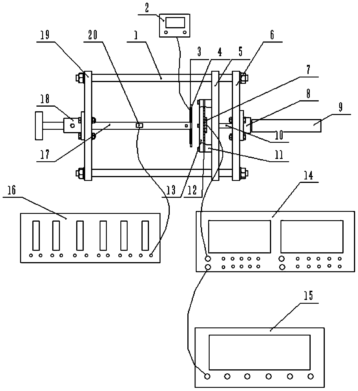
[0009] Embodiments of the present invention will be described in detail below in conjunction with the accompanying drawings. A device for measuring torsional shear force of material surface and ice layer adhesion strength includes micrometer head 9, temperature controller 2, power amplifier 14, signal generator 15 and strain gauge 16, on four axes arranged parallel to each other The left flat plate 19 and the right flat plate 6 are respectively fixed on the ends of the two sides of the rod 1, and the torque shaft 17 is rotatably supported by the support sleeve 18 on the left flat plate 19, and the aluminum plate 4 is installed on the right end of the torque shaft 17. , the right end surface of the aluminum plate 4 is pitted, the heating plate 3 is assembled on the left end surface of the aluminum plate 4, the rosette 20 is attached to the torque shaft 17, and the wire connects the temperature controller 2 with the heating plate 3 and the strain gauge 16 It communicates with th...


PUM


Abstract

The invention discloses a torsional shear force measurement device for the adhesion strength between material surfaces and an icing layer, and belongs to detection instruments. A left flat plate and aright flat plate are fixedly installed on the two end parts of a shaft rod respectively; a torque shaft is installed on the left flat plate in a rotatable mode; an aluminum plate with a heating sheetis installed on the right end of the torque shaft; a strain rosette is attached to the torque shaft; wires are used for communicating a temperature controller with the heating sheet, and communicating a strain gauge with the strain rosette; a micrometer head is assembled on the right flat plate; a seat plate is installed on the shaft rod in a transversely movable mode; a frame type support is installed on one side surface, opposite to the aluminum plate, of the seat plate; a material sample plate and an ice layer frame are assembled on the frame type support; and the axis of the torque shaftis overlapped with the telescopic rod axes of the aluminum plate, the ice layer frame, the material sample plate and the micrometer head. The device realizes the detection and analysis of the adhesionstrength between different material surfaces and the icing layer by detecting torsional shear force, and has the characteristics of being novel, reasonable and simple in structure, low in manufacturing cost, simple and convenient to operate and high in measuring precision.

Description

technical field [0001] The invention belongs to detection instruments, and mainly relates to a torsional shear force detection device for the adhesion strength between different materials and ice-coated layers. Background technique [0002] At present, scholars at home and abroad have conducted a lot of research on the measurement of the adhesion strength between the material surface and the ice layer, and the measurement techniques are mainly static measurement method and dynamic measurement method. Among them, the measuring device used in the static measurement method uses tensile force to measure the adhesion strength and shear force between the surface of the material and the ice layer. When testing, it is necessary to control the direction of the pulling force to be parallel to the shear plane, which is difficult to operate and requires the ice layer If the thickness is large, otherwise there will be measurement errors; the dynamic measurement method is to use the rotat...

Claims


Application Information

Patent Timeline
Patent Type & Authority Applications(China)
IPC IPC(8): G01N19/04G01N3/24G01M7/02
Inventor 李岩董笑宇郭文峰冯放
Owner NORTHEAST AGRICULTURAL UNIVERSITY
Why Eureka
Try Eureka