
Method for detecting direct-current magnetic bias of transformers

A DC bias and transformer technology, applied in the direction of measuring electrical variables, instruments, measuring electricity, etc., can solve problems such as the influence of transformer work, the increase of total magnetic flux density, and the asymmetry of positive and negative half waves, so as to reduce economic and social problems. Loss, improve the correct operation rate, improve the effect of power supply reliability

Pending Publication Date: 2019-06-14
STATE GRID SHAANXI ELECTRIC POWER RES INST +1
View PDF7 Cites 1 Cited by
  • Summary
  • Abstract
  • Description
  • Claims
  • Application Information

AI Technical Summary

Problems solved by technology

For half a cycle with the same DC bias direction, the magnetic flux density of the total magnetic flux will increase greatly, and the corresponding excitation current will increase significantly, showing positive and negative half-wave asymmetry, severe distortion of the waveform, and sharp peaks in the positive half-wave and will produce overshoots. The excitation phenomenon will also have a bad influence on the work of the transformer.
In addition, when the commutation of the DC system fails, the current of the AC system can be regarded as a harmonic source at this time. When an internal fault occurs at this time, the differential protection of the transformer will also work with a delay due to the existence of the second harmonic in the differential current. refuse to move

Method used


Image

  • Method for detecting direct-current magnetic bias of transformers
  • Method for detecting direct-current magnetic bias of transformers
  • Method for detecting direct-current magnetic bias of transformers

Examples


Embodiment

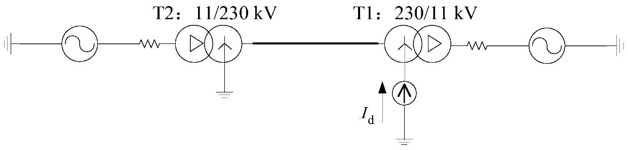
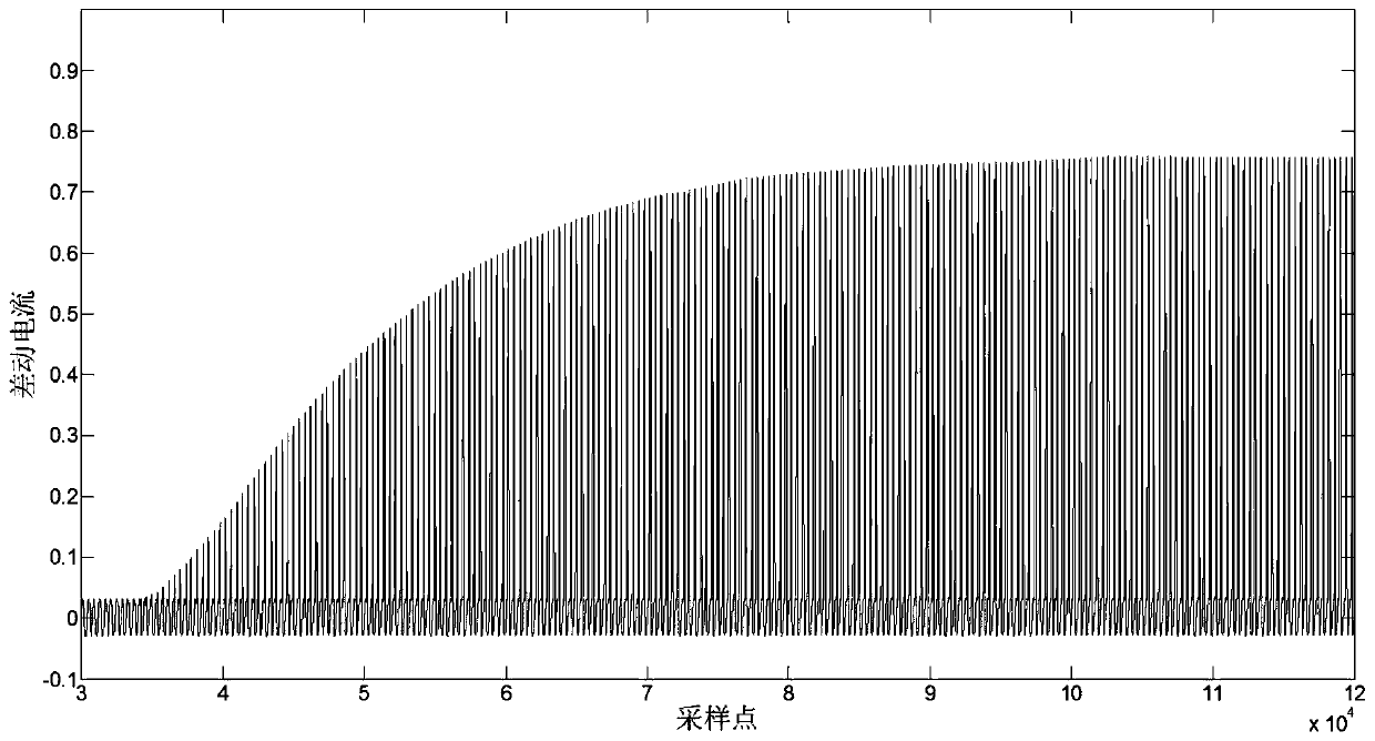
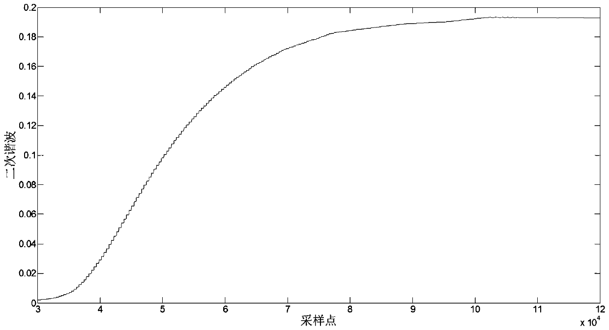
[0033] The PSCAD simulation model of DC bias is as follows: figure 1 As shown, the voltage level of the two transformers is 230kV, the rated capacity is 100MVA, and each power frequency cycle has 400 sampling points. Inject DC I from the transformer ground point d , as figure 2 The differential current waveform shown (unit: A). The direct current in the ground and the saturation of the iron core of the DC bias magnetic transformer do not appear at the same time, and there is a certain delay. It can be seen from the figure that the iron core of the transformer caused by the DC bias is saturated, the transformer first enters saturation from unsaturated, until it reaches a saturated stable state, and the amplitude of the second harmonic gradually increases with the degree of saturation until it is stable, as shown in image 3 shown. Such as Figure 4 In the no-load closing excitation inrush current of the transformer shown, the saturation of the iron core is caused by the a...


PUM


Abstract

The invention discloses a method for detecting direct-current magnetic bias of transformers. The method comprises the following steps: firstly judging that the transformers are saturated through a differential protection device and calculating secondary harmonic wave of differential current of the transformers; then researching attenuation condition of the secondary harmonic wave; enabling the secondary harmonic wave to be rapidly attenuated in allusion to iron core saturation caused by switching-in of the transformers under general conditions, and appropriately reducing a threshold value if the harmonic wave is slowly attenuated by system parameters accessed to the transformers; and enabling the content of the secondary harmonic wave to be increased or become a constant value in allusionto iron core saturation caused by direct-current magnetic bias. The method is capable of rightly distinguishing iron core saturation caused by direct-current magnetic bias and no-load switching-in ofthe transformers and avoiding internal fault rejection actions caused by direct-current magnetic bias and other hidden risks that threaten the safe operation of the transformers; in addition, the reliable detection of the direct-current magnetic bias phenomenon can facilitate power plants or substations to make corresponding strategies for inhibiting direct-current magnetic bias; the power supplyreliability is improved; the economic and social losses are reduced.

Description

technical field [0001] The invention belongs to the field of power systems, relates to the technical field of transformer protection, in particular to a method for detecting DC bias magnetism of transformers. Background technique [0002] The operation mode of the DC transmission system includes two poles directly forming a circuit, and a single pole forming a circuit with the earth or metal. When the DC system is overhauled or a single-pole blocking fault occurs, the system will form a circuit through the earth. At this time, the direct current entering the ground will change the distribution of the surface potential, making the potentials of different grounding points of the AC grid different, and generating a potential difference between the two grounding points. The circuit will cause the DC bias of the transformer, which will have an adverse effect on the transformer and its protection equipment, and even cause some protection malfunctions or delayed actions. In additi...

Claims


Application Information

Patent Timeline
Patent Type & Authority Applications(China)
IPC IPC(8): G01R31/00
Inventor 左宝峰贺晓李宗博何安阳焦在滨郝治国
Owner STATE GRID SHAANXI ELECTRIC POWER RES INST
Learn More