
A vortex type cable cooling device

A cooling device and cable technology, applied in the direction of cable/conductor manufacturing, circuits, electrical components, etc., can solve problems such as poor cooling effect, achieve the effect of increasing cooling effect, lengthening path, and reducing temperature

Active Publication Date: 2020-07-24
金华八达集团有限公司 +1
View PDF11 Cites 0 Cited by
  • Summary
  • Abstract
  • Description
  • Claims
  • Application Information

AI Technical Summary

Problems solved by technology

[0004] The purpose of the invention is to provide a vortex type cable cooling device with good cooling effect in order to overcome the disadvantage of poor cooling effect in the prior art

Method used


Image

  • A vortex type cable cooling device
  • A vortex type cable cooling device
  • A vortex type cable cooling device

Examples


Embodiment Construction

[0018] The present invention is further elaborated in detail in conjunction with the accompanying drawings and specific embodiments:

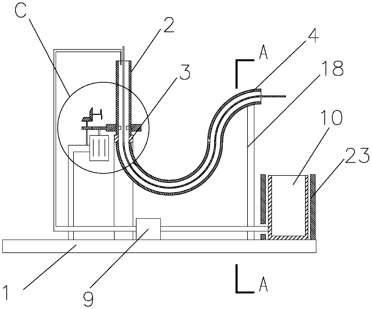
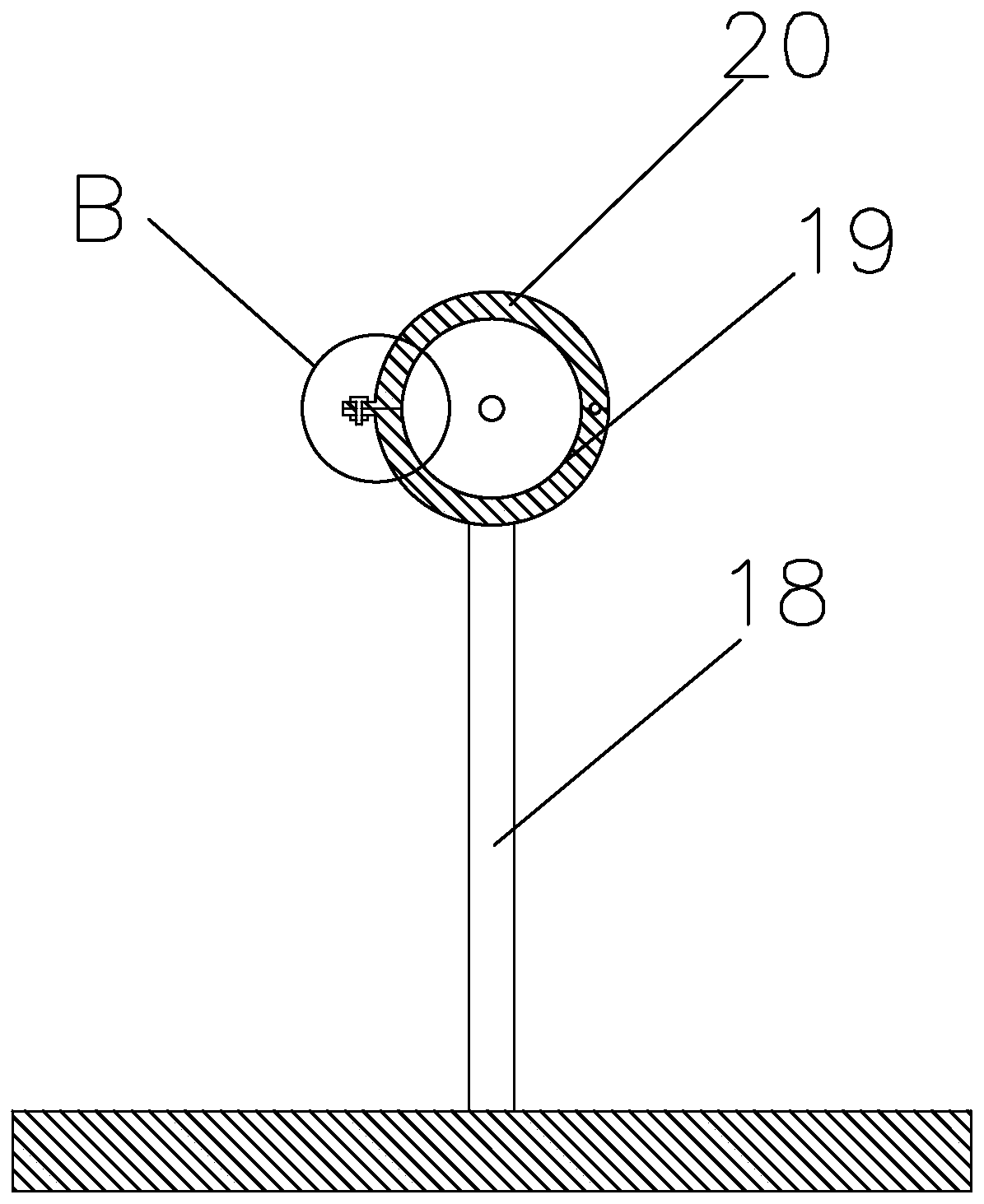
[0019] figure 1 and Figure 4 It is a vortex-type cable cooling device, including a base 1, on which a vertical rotating tube 2, an adapter sleeve 3 and a corrugated tube 4 are arranged, and the bottom end of the rotating tube 2 is connected through an adapter The sleeve 3 is connected to one end of the bellows 4, the adapter sleeve 3 is rotationally connected to the rotating pipe 2, the adapter sleeve 3 is fixedly connected to the bellows 4, the base 1 is provided with a pillar 18, and the bottom of the pillar 18 The end of the bellows 4 is fixed on the base 1, and the end of the bellows 4 away from the adapter sleeve 3 is connected to the top of the pillar 18, and the level of the end of the bellows 4 away from the adapter sleeve 3 is lower than that of the top of the rotating tube 2. , the adapter sleeve 3 is affixed to the base 1, a numbe...


PUM


Abstract

The invention discloses a swirl-type cable cooling device and relates to the field of cable manufacturing. The swirl-type cable cooling device comprises a base, wherein a vertical rotary pipe, an adaptive sleeve and a corrugated pipe are arranged on the base, struts are arranged on the base, a plurality of water stirring plates are fixedly connected to the inner sidewall of the bottom end of the rotary pipe, a first gear coaxial to the rotary pipe is fixedly connected to the rotary pipe, a driving gear is meshed with one side of the first gear, a water pipe is inserted into the top end of therotary pipe, a cooling water recycle trough and a water pump are arranged on the base, the cooling water recycle trough is located below the end, away from the adaptive sleeve, of the corrugated pipe,a fan gear is meshed with one side of the driving gear, a first transition rod coaxial to the fan gear is fixedly connected to the fan gear, a first bevel gear coaxial to the first transition rod isfixedly connected to the first transition rod, a second bevel gear is meshed with one side of the first bevel gear, a second transition rod coaxial to the second bevel gear is fixedly connected to thesecond bevel gear, a fan is arranged at one side of the rotary pipe, and the second transition rod is connected with the fan. The swirl-type cable cooling device has a good cooling water effect.

Description

technical field [0001] The invention belongs to the field of cable manufacturing, in particular to a vortex type cable cooling device. Background technique [0002] The cable processing process includes cable core manufacturing and sheath manufacturing. In the manufacturing process, the cable core and sheath are generally molded together by a high-temperature extruder. Therefore, a certain cooling is required after extrusion. [0003] National Patent Authorization Publication No. CN206116098U, authorized publication date 20170419, discloses "a cable cooling device", including a cooling mechanism, the cooling mechanism is composed of a cooling tank and a bracket, the cooling tank is rectangular, and the inside of the cooling tank is provided with a plurality of Rollers, one end of the cooling tank is provided with a cable inlet, the cable inlet is provided with an inlet roller, the other end of the cooling tank is provided with a cable outlet and a return port, the cable outl...

Claims


Application Information

Patent Timeline
Patent Type & Authority Patents(China)
IPC IPC(8): H01B13/00H01B13/22B29C48/885H01B13/24
Inventor 胡建华沃建栋朱筱玮桑长青吴建伟杨忠成吴旭静林清柯
Owner 金华八达集团有限公司
Features
  • Generate Ideas
  • Intellectual Property
  • Life Sciences
  • Materials
  • Tech Scout
  • Unparalleled Data Quality
  • Higher Quality Content
  • 60% Fewer Hallucinations
Learn More