Fault recording device, decentralized fault recording system and method

A fault recording device and fault recording technology, applied to fault locations, circuit devices, information technology support systems, etc., can solve the problem of asynchronous sampling and recording of the fault recording device, failure of the fault recording device to occupy the screen cabinet, and wave recording Data lack of redundancy and other issues, to achieve the effect of improving reliability, saving floor space, and small device size

Active Publication Date: 2019-06-14
CHINA SOUTHERN POWER GRID COMPANY +1
View PDF5 Cites 7 Cited by
  • Summary
  • Abstract
  • Description
  • Claims
  • Application Information

AI Technical Summary

Problems solved by technology

[0011] The technical problem to be solved by the present invention is: the centralized fault recording device occupies a special screen cabinet, the recording data lacks redundancy, and the sampling of the recording devices in each small room Due to the disadvantages of being out of sync with the recording and the inconvenient data exchange between recording devices under the star structure centered on the background management unit of the recording, a fault recording device and a decentralized fault recording system are proposed and method, according to the distributed configuration of analog and switch input channels, Ethernet redundant dual-network connection is used between each wave recording device, and time synchronization and synchronization are carried out by using a delay-measurable network method, and any wave recording device can be started A solution that triggers other wave recording devices to start synchronously, and can view the wave recording data of all wave recording devices through network access from any wave recording device

Method used


Image

  • Fault recording device, decentralized fault recording system and method
  • Fault recording device, decentralized fault recording system and method
  • Fault recording device, decentralized fault recording system and method

Examples


specific Embodiment

[0093] A specific embodiment of a decentralized fault recording method of the present invention comprises the following steps:

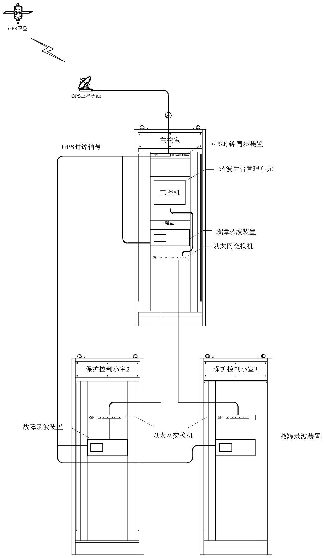
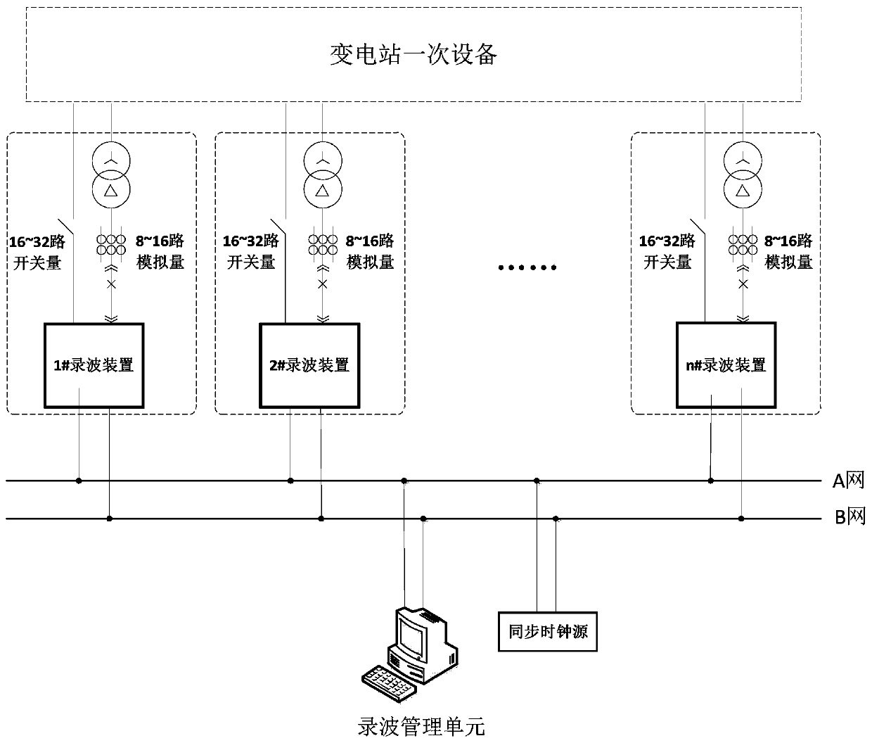
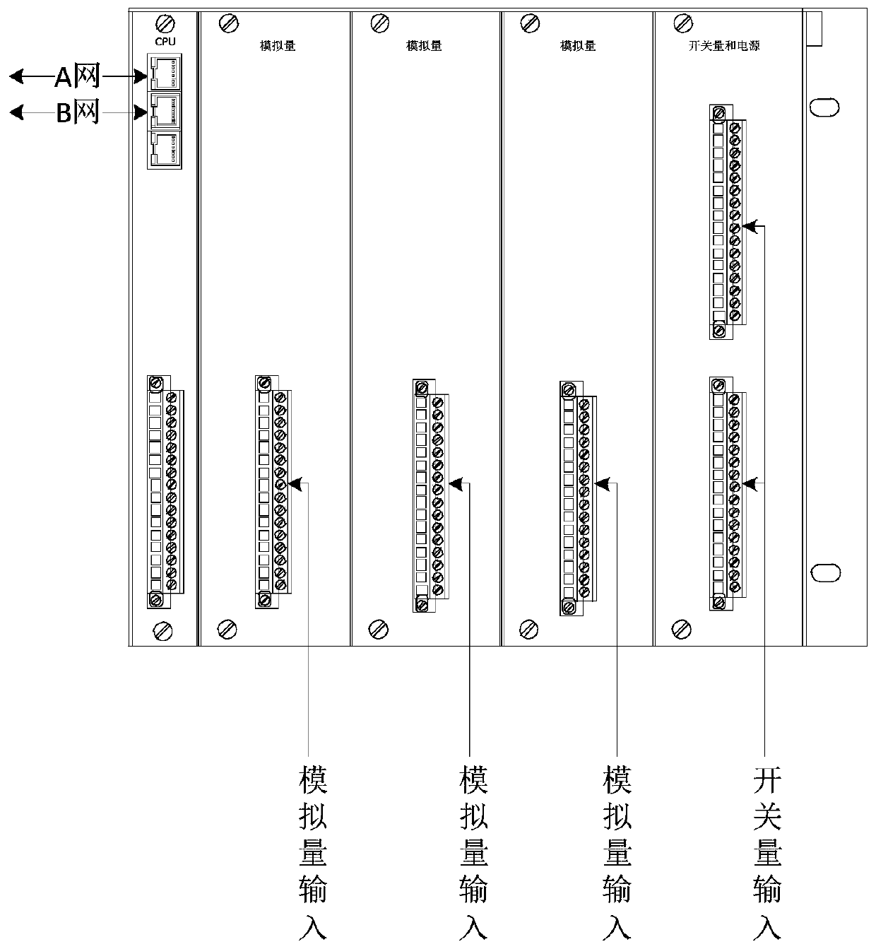
[0094] Step 1: Each interval is equipped with a fault recording device, which is responsible for collecting and recording its own wave recording data; the fault recording device is installed in an idle position of the protection screen cabinet, and does not occupy the screen cabinet separately; each fault recording device At least 8 channels of analog signals and 16 channels of switching signals are collected; the fault recording device is provided with two network ports A and B;

[0095] Step 2: Ethernet redundant dual-network connection is adopted between each fault recording device, A and B dual networks are established through independent switch equipment, and A port and B port of each device are respectively connected to A and B networks. There is no data exchange between B networks;

[0096] The two network ports of the fault recorder send the...


PUM


Abstract

The invention discloses a fault recording device, a decentralized fault recording system and a method. The scheme is a recording device which is freely arranged according to the input channel of analog quantity and switch quantity, dual-network redundant connection is conducted between devices, network synchronization can be carried out through measurable time delay, inter-device network triggering is performed, each device records and sends its own sample data, and also records sample data sent by other devices, and access from any device can view the technical realization scheme of the decentralization of all data. As the invention is different from the traditional fault recording realization scheme, the invention has the following characteristics: configuring by channel number saves screen cabinets, double network redundancy improves the reliability of the connection, the delay measurable network timing saves the connection lines and interfaces, the network synchronous triggering realizes the panoramic capture of disturbing data, the redundant records of each device improve the reliability of the data, and the access to all data at any point solves the problem that the recordingdevices of the protection and control room cannot access each other directly.

Description

technical field [0001] The invention belongs to the technical field of power systems and automation thereof, and relates to power grid relay protection technology, in particular to a fault recording device, a decentralized fault recording system and a method. Background technique [0002] The power system fault recording device is a device for collecting, recording and analyzing signals such as current, voltage and switching value of the power system. The action behavior of safety automatic devices provides assistance for disturbance analysis and fault handling. As a "black box" for recording grid faults or abnormal conditions, the fault recording device is an important basis for grid fault analysis. [0003] The earliest fault recording method is optical wave recording. The power system disturbance signal drives a vibrator, and the light beam on the vibrator exposes the moving film to leave a light track, which basically reflects the track of system signal changes. After...

Claims


Application Information

Patent Timeline
Patent Type & Authority Applications(China)
IPC IPC(8): H02J13/00H02H1/00G01R31/08
CPCY04S40/124Y02E60/00
Inventor 周红阳王亮黄佳胤吕航徐鹏侯学勇张驰余乾丁晓兵熊蕙余江鲁振威刘千宽高宏慧史泽兵郑茂然彭业
Owner CHINA SOUTHERN POWER GRID COMPANY
Why Eureka
Try Eureka