Two-stage single-phase three-level T-type asymmetric inverter, control method and device

A control method and inverter technology, which are applied to output power conversion devices, electrical components, and the conversion of AC power input to DC power output, etc., can solve the problems of clamping diode power loss, current distortion, endangering equipment personal safety, etc.

Active Publication Date: 2021-01-26
GUANGDONG UNIV OF TECH
View PDF6 Cites 0 Cited by
  • Summary
  • Abstract
  • Description
  • Claims
  • Application Information

AI Technical Summary

Problems solved by technology

At the same time, under the high-frequency switching action of the inverter, a common-mode current will be generated. When the common-mode current flows through the resonant circuit, the parasitic capacitance of the photovoltaic array to the ground will generate a leakage current. The leakage current will not only reduce the grid-connected current quality, causing current distortion, increasing harmonics and losses, and also bringing electromagnetic interference problems, reducing system safety and reliability, and even endangering equipment and personal safety
[0003] At present, the commonly used inverter is a two-stage single-phase three-level I-type asymmetrical inverter, please refer to figure 1 , figure 1 It is the post-stage structure of the post-stage I-type circuit in the two-stage single-phase three-level I-type asymmetrical inverter in the prior art, and the post-stage structure of the post-stage I-type circuit of the inverter adopting this structure need to add clamping diodes, such as figure 1 D in 3 and D 4 (i.e. the diode in the dotted box), and increase the clamping diode D 3 and D 4 Not only will it increase the cost, but the clamp diode will also have power loss

Method used


Image

  • Two-stage single-phase three-level T-type asymmetric inverter, control method and device
  • Two-stage single-phase three-level T-type asymmetric inverter, control method and device
  • Two-stage single-phase three-level T-type asymmetric inverter, control method and device

Examples


Embodiment Construction

[0051] The following will clearly and completely describe the technical solutions in the embodiments of the present invention with reference to the accompanying drawings in the embodiments of the present invention. Obviously, the described embodiments are only some, not all, embodiments of the present invention. Based on the embodiments of the present invention, all other embodiments obtained by persons of ordinary skill in the art without making creative efforts belong to the protection scope of the present invention.

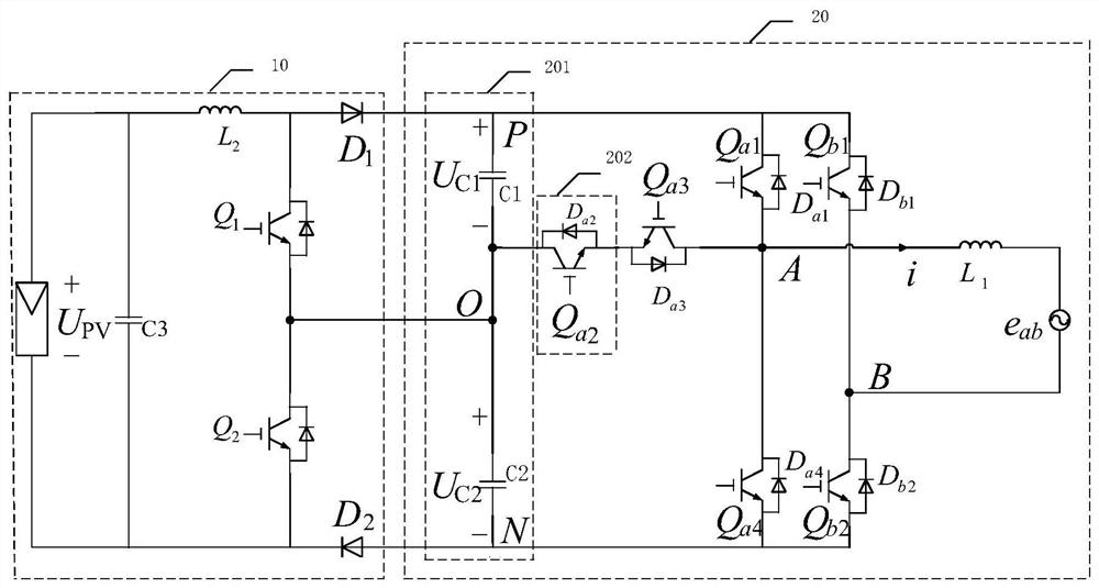
[0052] The embodiment of the invention discloses a two-stage single-phase three-level T-shaped asymmetrical inverter and a control method, which avoids adding clamping diodes and power loss caused by adding clamping diodes.

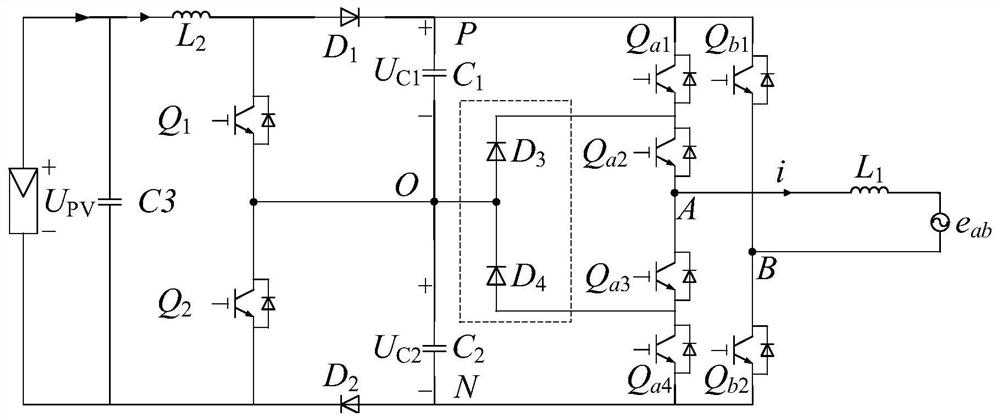
[0053] See figure 1 , figure 1 It is a schematic diagram of the post-stage structure of the post-stage I-type circuit in the two-stage single-phase three-level I-type asymmetrical inverter in the prior art. On the one hand, the post-stag...


PUM


Abstract

The invention discloses a two-stage single-phase three-level T-type asymmetrical inverter, comprising: a three-level Boost converter and a single-phase T-type asymmetrical inverter connected with the three-level Boost converter, Due to the adoption of the T-type circuit in the present application, compared with the I-type circuit in the prior art, there is no need to add clamping diodes, which reduces the cost and avoids power loss, and also simplifies the circuit structure. The invention also discloses a control method for the inverter. By adopting the provided control method, the value of the obtained common-mode voltage is relatively single. The common-mode voltage value changes less frequently within the predetermined period, and because the voltage value changes less frequently within the predetermined period, the corresponding leakage current is also relatively small, which ensures the normal operation of the inverter. In addition, the invention also discloses a control device for the inverter, which has the above effects.

Description

technical field [0001] The invention relates to the technical field of power electronics, in particular to a two-stage single-phase three-level T-shaped asymmetrical inverter, a control method and a device. Background technique [0002] With the rapid development of photovoltaic power generation, as the core equipment of photovoltaic system and grid interface, photovoltaic inverter has become a research hotspot in its topology and control mode. In the non-isolated photovoltaic grid-connected inverter, there is a large ground-to-ground parasitic capacitance between the photovoltaic array and the ground, forming a common-mode resonant circuit composed of parasitic capacitance, filter elements and grid impedance. At the same time, under the high-frequency switching action of the inverter, a common-mode current will be generated. When the common-mode current flows through the resonant circuit, the parasitic capacitance of the photovoltaic array to the ground will generate a leak...

Claims


Application Information

Patent Timeline
Patent Type & Authority Patents(China)
IPC IPC(8): H02M7/5387H02M7/483
Inventor 周浩武小梅张志庾锦培
Owner GUANGDONG UNIV OF TECH
Why Eureka
Try Eureka